ARMY
TM 5-6115-612-34
MARINE CORPS TM 6115-34/8
AIR FORCE
TO 35C2-3-471-2
NAVY
AG-320BO-MME-OOO
5-1.
GENERAL. (cont)
much
lower in
the conductor,
the
magnetic field changes so that it
spends
the maximum distance in the
conductor.
This causes the lines of
magnetic force to move so they pass
through the conductors in the stator.
As these magnetic lines of force move
across the conductors,
they generate
the output voltage. The output voltage
depends on
the number of lines per
second of magnetic
field that move
across the conductors.
By controlling
the speed of the generator (the rate at
which the lines move) and the strength
of the field (the number of lines), the
output voltage is controlled.
This is
the method used on brushless gener-
ators. As
shaft
and
rotor
speed
increase,
alternating
current is
produced and
flows from the stator
housing through diodes mounted in the
rectifier
plate.
The
diodes
and
rectifier plate change the alternating
current to pulsating direct current.
The
pulsating
direct
current
then
passes through a bus bar to the filter
box where the pulses are removed from
the pulsating direct
current.
The
resulting current is then ready for use
as starting power for aircraft.
5-2.
GENERATOR ASSEMBLY MAINTENANCE.
a.
Installed Test.
(1) Ensure that MASTER SWITCH
in OFF position.
is
WARNING
To prevent injury, ensure that
battery is
disconnected before
performing
maintenance
on
electrical components.
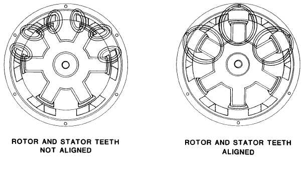
Figure 5-2.
Generator Conduction - Rotor and Stator Alinement
5-2