ARMY
TM 5-6115-612-34
MARINE CORPS TM 6115-34/8
AIR FORCE
TO 35C2-3-471-2
NAVY
AG-320BO-MME-OOO
CHAPTER 5
MAINTENANCE OF ELECTRICAL POWER GENERATION SYSTEM
5-1.
GENERAL.
The purpose of the
rotor rotates,
the magnetic lines of
generator (figure 5-1) is to convert
force cut across the conductor in the
mechanical
energy
into
electrical
output winding of the stator.
This
energy in the form of direct current.
generates the output power. Rectifiers
The generator is of brushless design
are used to change ac into dc when a dc
and rated at 10kW, 28 Vdc, 350 amps
output is desired.
This generator is
steady state.
Mechanical energy is
different in that it has no rotating
supplied by the rotating shaft of the
magnets or wires.
Both the field
turbine engine.
The shaft turns a
winding and output winding are located
rotor inside the stator housing of the
in the stator.
The rotor consists of a
generator.
All generators work by
slotted cylinder made of a material
causing magnetic lines of force to move
that conducts magnetic lines of force
across a conductor.
This is normally
easily.
As the teeth on the rotor
accomplished by moving the magnet or
aline with those on the stator,
the
the wire.
Most brushless generators
magnetic field takes the path of least
work by using a rotary transformer with
resistance and is concentrated in the
one winding on the rotor to transfer
conductor.
As it rotates, the teeth in
power to the rotor.
This power is
the rotor aline with the slots in the
rectified and is used to generate the
stator
(figure
5-2).
Since
the
magnetic field in the rotor.
As the
resistance to a magnetic field is so
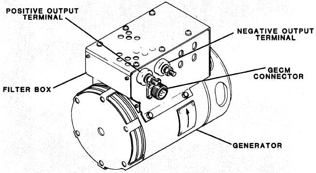
Figure 5-1.
Generator and Filter Box
5-1