TM 5-6115-590-12
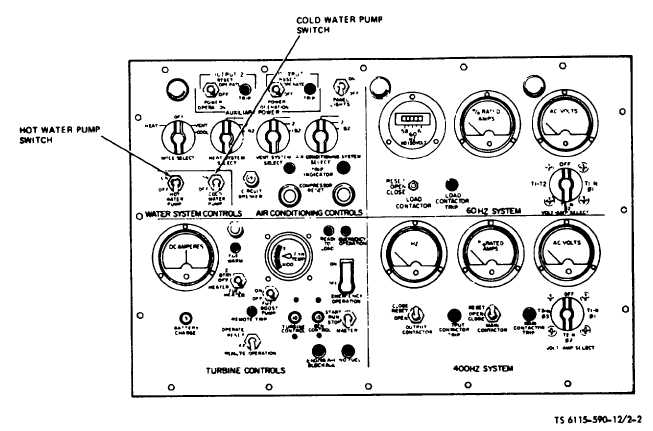
Figure 2-2. Instrument Panel (Water System Controls). (TS 6115-590-12/2-2).
b. Auxiliary Power Switches (two used: output 1 and
output 2).
(1) Description. A three position toggle switch.
(2) Purpose. Energize and de-energize auxiliary power
outputs 1 and 2 and prevent operation of one
conditioned air system when one auxiliary output is
operated or both conditioned air systems when both
auxiliary outputs are operated. Also resets the 400 Hz
auxiliary output when tripped.
2-5.
Conditioned
Air
System
Controls
and
Instruments
The conditioned air system controls and instruments are
located on the upper left of the instrument panel (fig
2-4). the conditioned air circuit breaker panel (fig 2-5).
and the conditioned air temperature control panel (fig
2-6) The description and function of the conditioned air
system controls and instruments are described as
follows:
a. Panel Illumination Lamps (fig 2-4).
(1) Description. The three panel illumination lamps are
hooded filament type lamps. The hoods are adjustable
for directing the illumination on the panel.
(2) Purpose. Illuminates the instrument panel for night
operation.
b. Panel Lights Switch.
(1) Description. A two position ON-OFF toggle switch.
(2) Purpose. Energizes and de-energizes the three
panel illumination lamps
c. Conditioned Air Mode Select Switch.
(1) Description. A four position rotary switch.
(2) Purpose. Selects the type of conditioned air (heat
vent cool or off) as desired to be delivered from the
conditioned air system.
d. Heat System Select Switch.
(1) Description. A three position rotary switch0.
(2) Purpose. Selects the No. 1 system, the No. 2
system, or the No. 1 and the No. 2 system combined to
deliver heated air as described to meet heated air output
requirements.
e. Vent System Select Switch.
(1) Description. A three position rotary switch
(2) Purpose. Selects the No. 1 system, the No. 2
system, or the No 1 and the No. 2 system
2-4


