TM 5-6115-590-12
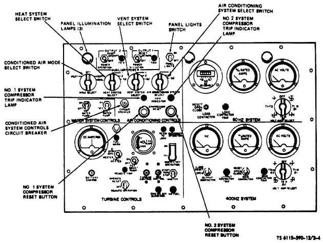
Figure 2-4. Instrument Panel (Conditioned Air System Controls). (TS 6115-590-12/2-4).
(2) Purpose. Illuminates to indicate that the power
contactor to the No. 2 system compressor has tripped to
open the power circuit to the compressor motor.
NOTE
The press-to-test feature of the air conditioning
compressor trip indicators (system 1 and 2) allow
operator to check circuit (Bulb). They are to be checked
only with the unit in operation and main 400HZ contactor
closed.
l. Recirculating Fan Circuit Breaker (No. 1 system) (fig.
2-5).
(1) Description. A press-to-reset circuit breaker installed
in the No. 1 system recirculating fan power circuit.
(2) Purpose. Provides short circuit and over. load
protection for the No. 1 system recirculating fan power
circuit. The circuit breaker opening amperage (20
amps) is marked on the reset button.
m. Condenser Fan Circuit Breaker (No. 1 system).
(1) Description. A press-to-reset circuit breaker installed
in the No. 1 system condenser fan power circuit.
(2) Purpose. Provides short circuit and over load
protection for the No. 1 system condenser fan power
circuit. The circuit breaker opening amperage (50
amps) is marked on the reset button.
n. Deleted
o. Recirculating Fan Circuit Breaker (No. 2 system) (fig.
2-5).
(1) Description. A press-to-reset circuit breaker installed
in the No. 2 system recirculating fan power circuit.
(2) Purpose. Provides short circuit and over load
protection for the No. 2 system recirculating fan
2-6
Change 6