TM 5-6115-590-12
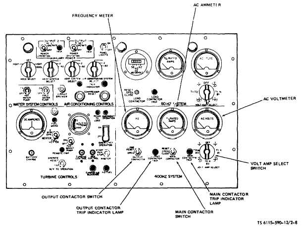
Figure 2-8. Instrument Panel (400 Hz Electrical). (TS 6115-590-12/2-8).
a. Frequency Meter.
(1) Description. Dial pointer gauge, calibrated to
indicate 388 to 412 hertz per second in 1/2 hertz per
second increments. The dial scale has a red index mark
at 400 hertz per second.
(2) Purpose. To indicate the output frequency of the
400 Hz electrical system.
(3) Indication. Normal indication is 400 Hz per second.
b. AC Ammeter
(1) Description. Dial pointer gauge, calibrated to
indicate percent of rated current. The dial is calibrated
from 0 to 125 percent in 5 percent increments.
(2) Purpose. To indicate the line-to-neutral current as
selected through the volt-amp select switch during
operation of the power unit
(3) Indication. Normal operating range Is 0 to 100
percent. Ammeter readings over 100 percent indicate
an overload condition.
c. AC Voltmeter
(1) Description. Dial pointer gauge, calibrated to
indicate 0 to 150 V AC m 5 volt increments.
(2) Purpose. Indicates line-to-neutral voltages, as
selected through the volt-amp select switch during
operation of the power unit.
(3) Indication. Normal operating indication Ls 120V AC,
as determined by the position of the volt-amp select
switch.
d. Volt-Amp Select Switch.
(1) Description. A four position rotary stitch.
(2) Purpose. Connects the AC ammeter and AC
voltmeter for selective monitoring of the line-to-neutral
voltages and currents An OFF position is also provided
to disconnect the ammeter and voltmeter.
e. Output Contactor Switch.
(1) Description. A three position toggle switch.
(2) Purpose. In the momentary RESET position the
switch actuates the 400 Hz output contactor to reset and
close the output contacts connecting the 400 Hz
electrical system to the external load. When released,
the switch returns to the CLOSE position. In the OPEN
position the switch actuates the contactor to open the
output contacts and disconnect
2-10
Change 9