TM 5-6115-590-12
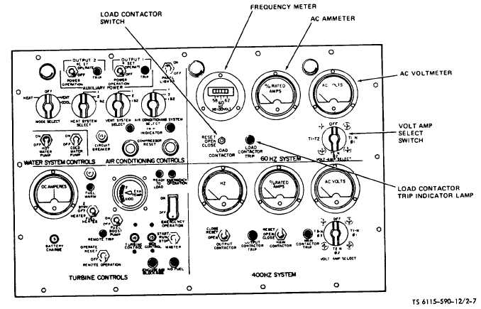
Figure 2-7. Instrument Panel (60 Hz Electrical). (TS 6115-590-12/2-7)
calibrated from 0 to 125 percent in 5 percent
increments. The dial range is colored red from 100 to
125 percent.
(2) Purpose. To indicate the line-to-line and line-to-
neutral current as selected through the volt-amp select
switch during operation of the power unit.
(3) Indication. Normal operating range is 0 to 100
percent. Ammeter readings over 100 percent indicate
an overload condition.
c. AC Voltmeter.
(1) Description. Dial pointer gauge, calibrated to
indicate 0 to 300V AC in 10 volt increments.
(2) Purpose. Indicates line-to-line and line-to-neutral
voltages, as selected through the volt-amp select switch
during operation of the power unit.
(3) Indication. Normal operating indication is 120 or
240V AC as determined by the position of the volt-amp
select switch.
d. Volt-Amp Select Switch.
(1) Description. A four position rotary switch.
(2) Purpose. Connects the AC ammeter and AC
voltmeter for selective monitoring of the line-to- line and
two-line-to-neutral voltages and currents. An OFF
position is also provided to disconnect the ammeter and
voltmeter.
e. Load Contactor Switch.
(1) Description. A three position toggle switch.
(2) Purpose. In the CLOSE position the switch actuates
the 60 Hz power output contactor to close, thus
connecting the 60 Hz electrical system to the external
load. In the OPEN position the switch actuates the
contactor to open and disconnect the load. In the
RESET position the switch resets the protective circuits
in the generator control panel if the load contactor trip
light is on.
f. Load Contactor Trip Indicator Lamp.
(1) Description. A filament type press-to-test lamp with
a red lens.
(2) Purpose. Illuminates to indicate that the load
contactor has tripped to disconnect the load from the 60
Hz electrical system.
2-7. 400 Hz Electrical System Controls and
Instruments (fig. 2-8)
The 400 Hz electrical system controls and instruments
are located on the instrument panel. The description,
purpose, and function of the 400 Hz electrical system
controls and instruments for the power unit 400 Hz
electrical system are described as follows:
2-9