TM 5-6115-590-12
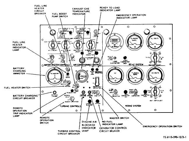
Figure 2-1. Instrument Panel (Gas Turbine Engine Controls and Instruments (TS 6115-590-12/2-1)
complete the starting sequence. The master switch also
functions as an engine stop switch by de-energizing the
engine 24V DC control circuit when placed in OFF
position.
CAUTION
Do not hold master switch in start position after engine
starts to rotate.
k. Generator Control Circuit Breaker.
(1) Description. A press-to-reset circuit breaker installed
in the 60 Hz and 400 Hz generator control circuits.
(2) Purpose. Provide short circuit and overload
protection for the generator control circuits The circuit
breaker opening amperage (15 amps) is marked on the
reset button.
I. Turbine Control Circuit Breaker.
(1) Description. A press-to-reset circuit breaker installed
in the engine control circuit.
(2) Purpose. Provides short circuit and overload
protection for the engine control circuit. The circuit
breaker opening amperage (10 amps) is marked on the
reset button.
m. Remote Operation Switch.
(1) Description. A three position toggle switch.
(2) Purpose. When placed in the OPERATE RESET
position, the switch completes a circuit to reset and
close an output contactor to deliver power to a
nonoperating power plant for operation of the ventilating
fans in the nonoperating unit. The switch returns to the
center position when released. When placed in the OFF
position, the switch opens the remote output contactor to
stop power output to the nonoperating unit.
n. Remote Operation Trip Indicator Lamp.
(1) Description. A filament type press-to-test lamp with
a red lens.
(2) Purpose. Illuminates to indicate that the remote
power output contact has tripped to open and
disconnected the remote load.
NOTE
Press-to-test feature only operates when unit is
operating and 400HZ contactor is closed.
2-2
Change 5


