TM 55-2835-209-23
5-4 REPLACE HOURMETER ASSEMBLY (CONT)
REMOVAL
1.
2.
3.
4.
NOTE
To aid in assembly, leads
should be marked prior to re-
moval.
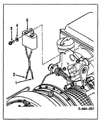
Cut and remove textile braids (D39A)
and slide sleeving up APU wiring
harness assembly to expose elec-
trical connectors (1, 2).
Disconnect electrical connectors (1,
2) from hourmeter assembly (5).
Remove bolts (3) and washers (4) se-
curing hourmeter assembly (5) to
meter bracket.
Remove hourmeter as-
sembly.
Clean hourmeter assembly (5) using
process 7, Chapter 8.
INSTALLATION
NOTE
Prior to assembly, all compo-
nents will be visually in-
spected for damage.
Position hourmeter assembly (5) on
meter bracket with counters in 12
o’clock position.
Secure with wash-
ers (4) and bolts (3). Torque bolts
to 38 to 42 inch-pounds.
Connect electrical connectors (1, 2)
to hourmeter assembly as marked.
Slide sleeving (D33) down and center
over each electrical connector (1,
2).
Deleted.
5.
Install textile braid (D39A) two
places on each sleeve covering con-
nectors (1, 2).
6.
Each textile braid (D39A) must be
0.20 to 0.30 inch from ends of
sleeve.
Tie in a square knot.
7.
Apply coating (D6A) to knot and ends
of textile braid (D39A).
FOLLOW-ON MAINTENANCE:
MOC required to
check event counter.
Change 1
5-11


