TM 5-6115-590-12
TS 6115-590-12/4-5
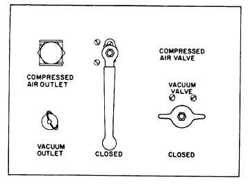
Figure 4-5. Compressed Air and Vacuum Connection and Control Panel (TS 6115-590-12/4-5).
(a)
Remove caps from surge tank, hot
water tank, and heat exchanger drains. Open hot water
return valve to allow any water in the system to drain,
then reinstall caps on drain fittings. Close hot water
return valve and check that all other valves are closed.
(b)
Open air temperature control panel
access door (fig. 1-1) and open the hot water tank vent
valve (fig. 1-11) on top of the hot water storage tank.
(c)
Connect a source of potable water
to the water inlet fitting utilizing the water supply and
drain hose (fig. 1-15, Sheet 3 of 7).
CAUTION
Be sure water supply and drain hose is not kinked,
collapsed, or otherwise positioned to restrict water
flow.
(d)
Connect a water hose to cold water
outlet fitting (fig. 4-4) and arrange hose to drain to a
convenient place.
(e)
Start gas turbine engine (para 2-10)
and place 400 Hz system main contactor switch in
CLOSED position,
(f)
Place hot water pump and cold
water pump switches on instrument panel to the ON
position.
(g)
Place cold water valve (fig. 4-4) in
OPEN position and observe water flow from hose
attached to cold water outlet fitting. Observe cold water
outlet and hot water tank vent drain for continuous flow
of water. When a continuous flow of water is observed
from cold water outlet and hot water tank vent drain,
close hot water tank vent valve (fig. 1-11) and place
cold water valve (fig. 4-4) in CLOSED position. The hot
water and cold water system is now fully primed.
NOTE
In the event the water system fails to prime, continue
with steps (h) and (i) Otherwise go to step (j)
(h)
Connect the vacuum hose to the
vacuum outlet on the power. Move the vacuum lever to
the ON position.
(i)
Open the cold water outlet hand
valve and place the vacuum hose over the water outlet
momentarily.
Repeat
this
procedure
until
full
pressurized water flow is observed at the cold water
outlet valve. The system is now primed.
(j)
Connect dual water hose assembly
(fig. 1-15, sheet 3 of 7) to hot water and cold water
outlet fittings (fig. 4-4).
NOTE
If
possible
freezing
conditions
are
anticipated connect electrical connectors
on supply and drain water hose assembly
(fig. 1-15, sheet 3 of 7) and dual water
hose assembly to water line heater
connectors on receptacle panel (fig. 2-9).
Connect electrical connectors on water
recirculating hose assembly to connectors
on the shelter Position and protect hose
assemblies to prevent kinks, collapse,
and damage from traffic.
4-6


