TM 5-6115-590-12
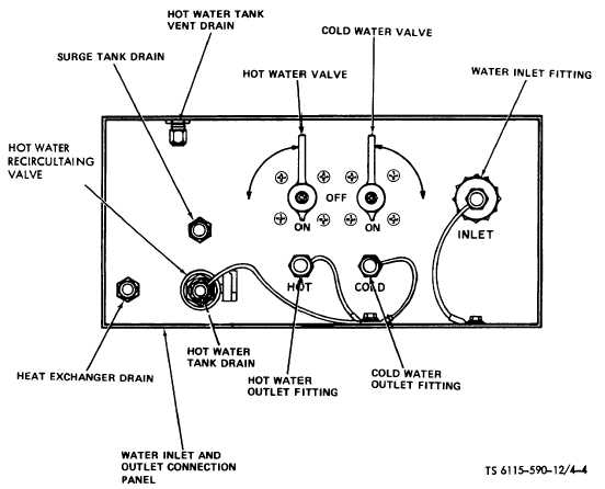
Figure 4-4. Water Inlet and Outlet Connection Panel (TS 6115-590-12/4-4).
CAUTION
Use care during installation of panel to
prevent damage to insulating foam
around edge of panel.
(c)
Install drain hoses on fittings in
bottom of divider panel and insulated collar around
heated air line and position hose behind heated air lines
as shown in fig. 4-3.
(4)
External 24V DC auxiliary power source
connections. If power plant batteries are discharged or
otherwise inoperative, connect an external 24V DC
auxiliary power source to the power unit as follows.
(a)
If external 24V DC power source
has a DC take off receptacle, connect external power
input cable assembly (fig. 1-15, sheet 1 of 7) to take off
receptacle and DC battery slave connection on
receptacle panel.
(b)
If an external battery or batteries
are used, install battery terminal lugs of external DC
power cable assembly (fig. 1-15, sheet 1 of 7) on
terminals with polarity marks (+ and -) on terminal lugs
matched to polarity marks on battery terminals.
Connect dc connector on electrical output connection
panel.
CAUTION
Do not attempt to operate power plant if batteries
are not connected.
NOTE
If polarity is reversed between external
battery and power plant the reverse
polarity indicating lamp will illuminate
indicating the condition and the power
plant
will
not
start.
Reverse
cable
assembly
terminal
lugs
on
battery
terminals to correct the condition.
(c)
After power plant is started (para
2-10), disconnect external DC power cable assembly.
(5)
Water system connections and priming.
Refer to fig. 4-4 and connect and prime system as
follows.
4-5