TM 5-6115-590-12
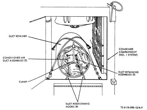
Figure 4-9. Stowing Accessory Components in Condenser Compartment (No 1 System) (TS 6115-590-12/4-9).
(k)
Place hot water valve (fig. 4-4) and
cold water valve in OPEN position and connect dual
water hose assembly to point of water use.
(l)
Connect one water recirculating
hose assembly (fig. 1-15, sheet 6 of 7) to hot water
return fitting (fig. 4-4) on the power unit and to the
return at point of water use. Connect the other water
recirculating hose between the return at point of water
use and the water source on the power unit for
circulation of cold water.
(m)
Place hot and cold water valves and
hot water return valve in OPEN position. Hot and cold
water delivery may now be taken at point of use.
NOTE
Check all outlet valves at point of water
use to insure that they are closed before
opening
valves
on
power
plant.
Approximately 15 minutes should elapse
before attempting hot water use to permit
water to be heated.
(6)
60 Hz power output connections. Use 60
Hz electrical power output cable assembly (fig. 1-15,
sheet 2 of 7) to connect between the 60 Hz power out.
put receptacle (fig. 2-9) and other elements of the
MUST hospital. Two 60 Hz convenience receptacles
(fig. 2-9) are also included on the receptacle panel to
provide 60 Hz power for external requirements. The
convenience receptacles will accommodate a standard
three-prong, twist-lock plug.
(7)
400 Hz power output connections. Use
400 Hz electrical power output cable assembly (fig.
1-15, sheet 2 of 7) to connect between the 400 Hz
power output receptacle (fig. 2-9) and other elements of
the MUST hospital. Two 400 Hz convenience
receptacles are also included on the receptacle panel to
provide 400 Hz power for external requirements. The
convenience receptacles accommodate standard three
prong, twist-lock plugs or parallel U-ground plugs.
(8)
400 Hz auxiliary power connections. If
400 Hz auxiliary power is required, connect 400 Hz
electrical power output cable assemblies (fig. 1-15,
sheet 2 of 7) to 400 Hz auxiliary power receptacle (fig.
2-9) and to 400 Hz power requirement.
NOTE
Conditioned air systems and auxiliary 400
Hz power outputs are interlocked to avoid
overload of the 400 Hz system. If one
auxiliary 400 Hz output is in use only one
of the conditioned air systems will
operate. If both auxiliary 400 Hz systems
are in use, neither conditioned air system
will operate.
4-10