TM 5-6115-590-12
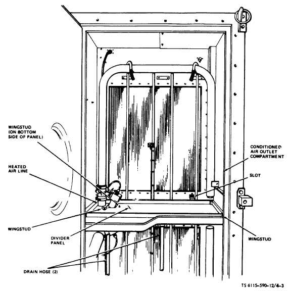
Figure 4-3. Conditioned Air Outlet Compartment Divider Panel Installation. (TS 6115-590-12/4-3).
(2)
Fuel supply connection. Connect external
fuel system filter assembly (fig. 1-15, sheet 5 of 7) to
fuel inlet fitting as shown in fig 4-2. Connect fuel hose
assembly between fuel supply and filter assembly.
Check fuel lines and fuel filter assembly for evidence of
leakage. Correct all leakage before proceeding with
installation connections.
NOTE
Fuel must be free flowing to fuel boost
pump. Use fittings listed on page C-2 to
connect fuel hoses directly to fuel tank.
(3)
Conditioned air outlet compartment divider
panel installation. Install divider panel and compartment
drain hoses (fig 1-15, sheet 4 of 7) in conditioned air
outlet compartment (fig 1-2) as follows.
(a)
Remove divider panel from battery
access and storage compartment (fig. 1-1) and remove
drain hoses secured to bottom of panel.
(b)
Open
conditioned
air
outlet
compartment access door and carefully install panel
with cutout in panel corner around heated air line
insulated collar in compartment, with left side of panel
engaging angle slots in brace on left side of
compartment (fig 4-3). Engage slots in rear edge of
panel with hook In wall of compartment Secure panel to
compartment with the three wingstuds.
Change 5
4-4


