TM 55-2840-254-23
1-19 ELECTRICAL AND IGNITION SYSTEM
A.
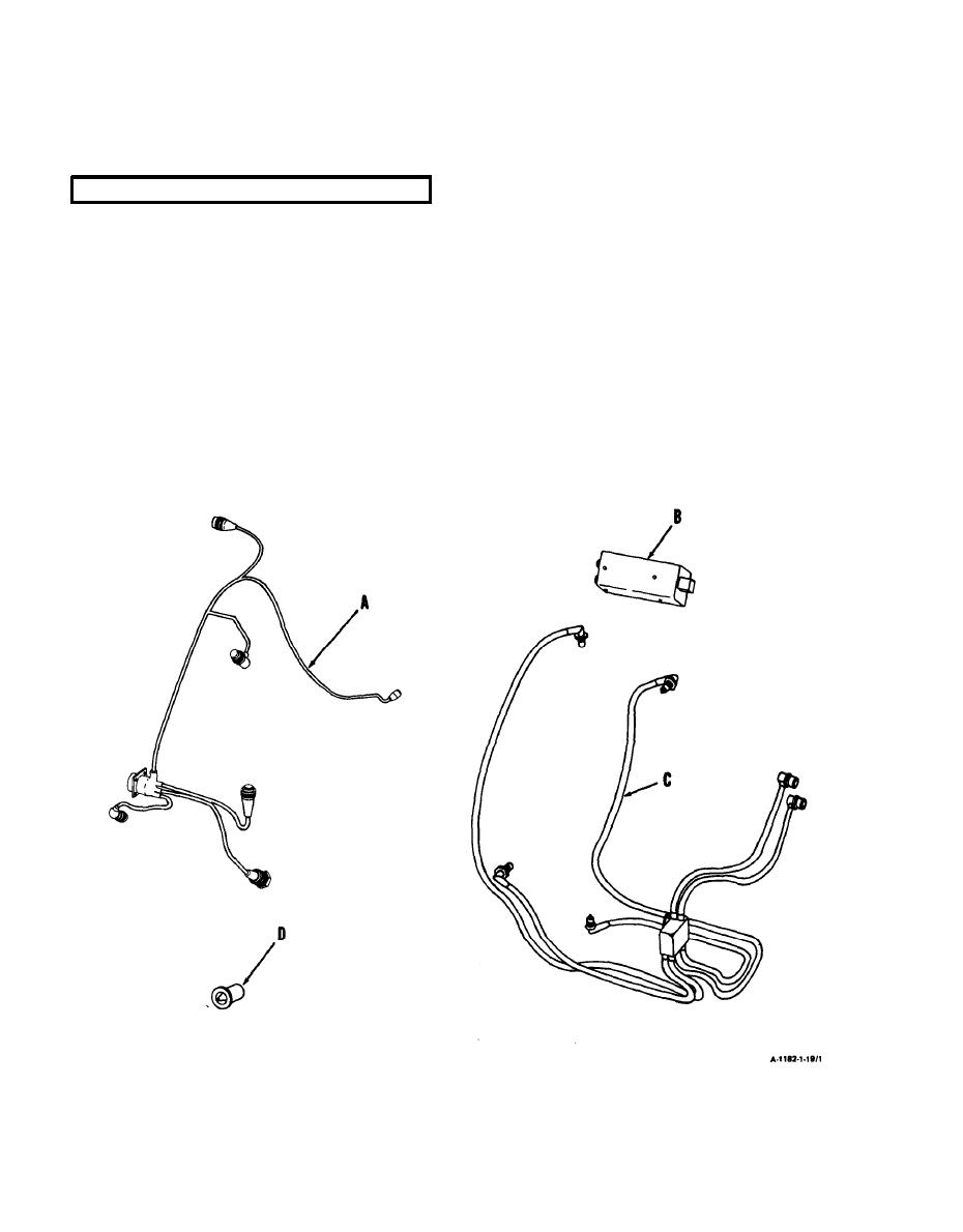
Provides circuitry for ignition, starting, and all electrial accessories. (Ref. Appendix D.) Components
are listed and keyed in the following diagram.
NOTE
Some engine Electrical Cable Assemblies may have 9 smaller
connectors. The two additional connectors are not used.
ELECTRICAL CABLE ASSEMBLY. Provides circuitry for electrical accessories. Consists of main
A
connector for airframe harness hookup and 6 smaller connectors for accessories.
IGNITION EXCITER. Mounts on brackets on right side of compressor housing, Provides high voltage
B
pulse required for ignition. Converts 24 volt input at 2.5 amperes current to 2500 volts.
COIL AND CABLE ASSEMBLY. Provides high voltage ignition wiring. Consists of shielded cabling
C
and transformer. Splits high voltages from ignition exciter and distributes them
equally to four spark igniters.
SPARK IGNITERS. Mount at approximately 12-, 3-,6-, and 9-o'clock positions near aft end of com-
D
bustor section. Provides spark discharge needed for ignition in combustion area.
1-32


