TM 55-2840-254-23
1-18 FUEL SYSTEM
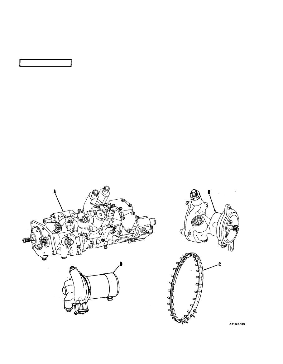
A. Controls and distributes fuel for engine operation. Components are listed and keyed in following
diagrams.
FUEL CONTROL. Hydromechanical device containing a fuel pump, two speed governors, an
A
acceleration and deceleration control, an air-bleed signal mechanism, and a
fuel shutoff valve. Single power lever connection provided to select desired
engine power from OFF to MAXIMUM power. Mounts on and is driven by
accessory gearbox assembIy.
FUEL BOOST PUMP. Contains single centrifugal impeller. Provides fuel pressure rise of 10 to 20
B
psi dictated by speed and flow conditions. Mounts on and is driven by accessory
gearbox assembly.
MAIN FUEL MAN I FOLD. Consists of two halves each having 14 main fuel nozzles. Mounts on
C
rear surface of combustor section. Nozzles insert through holes in combustor
section and into combustion area.
MAIN FUEL FILTER. Mounts on bracket on left side of compressor housing. Contains replace-
D
able filter element. Also contains popout indicator button .-Button pops out if
filter element is close to being bypassed because of clogging.
1-28


