TM 55-2835-208-23
2-82 INSTALL ENGINE ELECTRICAL HARNESS ASSEMBLY (Continued)
2-82
5.
6.
7.
7.1
8.
9.
10.
11.
12.
13.
13.1
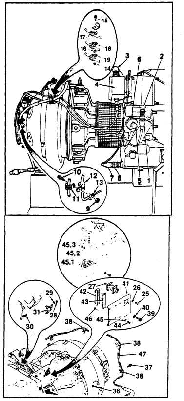
On APU PN 116305-100, -200, AND -201,
secure bracket (41) with screws (44), washers
(45), and nuts (46). Secure ground wire using
bolt and washer.
Secure
clamp (31) with bolt
(30), washer (29) and nut (28).
Secure
clamps (38) with bolts
(37) and nuts (36).
On APU PN 116305-300, and 16305-302,
wrap thermocouple and ignition leads at
mount positions of clamps (17 and 19) with
fiberglass tape (E34) to ensure proper clamp
fit.
Position clamps (17) and (12)
on harness assembly.
Secure
clamps (12) and (11) with bolt
(10) and nut (9).
Secure clamps (17, 18) and (19)
with bolt (15), spacer (16) and
nut (14).
Connect connector P302 (1) to
magnetic pickup (2).
Connect
connector
P303 (3) to
ignition exciter (4).
Connect
connector
P304 (5) to
low oil pressure switch (6).
Connect connector P310 (7) to
high
oil temperature
switch
(8).
On APU PN 116305-300 and l16305-302,
remove terminal board cover and connect
leads of meter assembly (45.1) to terminal
board as shown. Secure leads using tie-down
straw as required.
Install terminal board
cover.
GO TO NEXT PAGE
Change 5
2-153