TM 55-2835-208-23
2-20 INSTALL COMBUSTOR SECTION
2-20
INITIAL SETUP
Materials:
Applicable Configurations:
Lubricating Oil (E24)
Anti-Seize Compound (El 5)
All
Lockwire (E16)
Assembly Fluid, No. 1 (E31)
Tools:
Personnel Required:
Torque Wrench
NSN 5120-00-542-4489
68B Aircraft Powerplant Repairer
68B Powerplant Inspector
Engines Repairman’s Tool Kit
NSN 5180-00-323-4944
Combustor Puller (T3)
Combustor Puller Adapter (T11)
Alignment Tool (T25)
Parts:
Seal Ring
1.
2.
Equipment Condition:
APU in Assembly Fixture (Task 1-22)
3.
4.
5.
GO
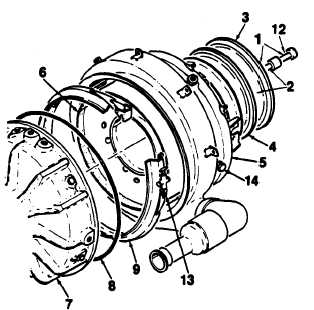
Assemble combustor puller (T3) (1) to
adapter (Tl1) (2) with clamp (3).
Install combustor puller (T3) (1) with
adapter (T11) (2)
onto combustor hous-
ing (5). Secure with pipe assembly ex-
haust clamp (4).
Apply a light coating of anti-seize com-
pound (E15) to mating surfaces of com-
bustor housing (6) and nozzle of turbine
assembly (7).
Apply assembly fluid (E31) to seal ring
(8) and install in air inlet housing groove
on turbine assembly (7).
Position clamp (9) on combustor housing
(5) .
TO NEXT PAGE
2 - 4 2Change 4