TM 5-6115-590-12
TS 6115-590-12/1-9
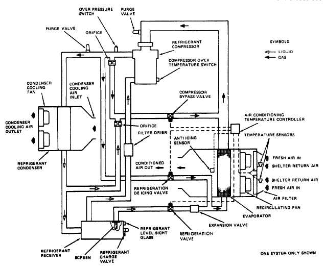
Figure 1-9. Cooled Air System Schematic. (TS 6115-590-12/1-9).
The accessory components consist of the following
items.
(1) One external battery DC power cable assembly
for connection of external battery from a military vehicle
equipped with a 24V DC output receptacle to the power
plant for auxiliary starting power.
(2) One external DC electrical power input cable
assembly for connection of an external 24V DC power
source.
(3) One DC electrical power input cable assembly
for connecting the 24V DC systems of two power units
together to provide for standby operation of one power
plant.
(4) One 400 Hz auxiliary power cable assembly for
connection between power plants for remote operation
of ventilating fans.
(5) One 400 Hz electrical power output cable
assembly for connection of the power plant 400 Hz
electrical system to other elements of the MUST
hospital as required.
(6) One 60 Hz electrical power output cable
assembly for connection of the power plant 60 Hz
electrical system to other elements of the MUST
hospital as required.
(7) One
compressed
air
hose
assembly
for
connection of the power plant compressed air outlet to
the MUST hospital inflatable elements for delivery of
inflation air.
(8) One electrically heated water supply and drain
water hose assembly for connection of an external water
source to the power plant water system.
(9) One
electrically
heated
dual
water
hose
assembly for connection of the power plant water
system to other elements of the MUST hospital.
(10)
One inflation ejector assembly used to inflate
the inflatable elements of the MUST hospital.
(11)
Eight conditioned air duct assemblies for
connection of the power plant conditioned air system to
other elements of the MUST hospital.
1-17


