TM 5-6115-590-12
TS 6115-590-12/1-8(1)
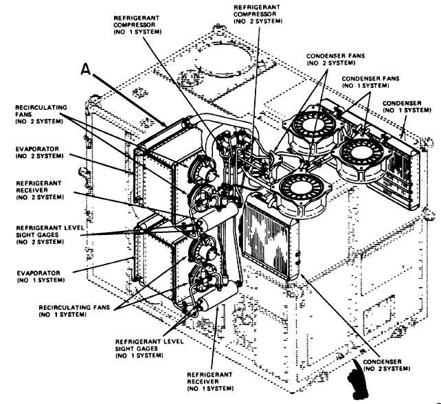
Figure 1-8(1). Conditioned Air System (Sheet 1 of 2). (TS 6115-590-12/1-81)
cleaner ejector flows continually to scavenge dust and
foreign material separated from the intake air by the
engine
air
cleaner
during
engine
operation.
Compressed air to heat the water tank compartment is
controlled by a thermostatic switch in the water tank
compartment and a solenoid valve in the compressed
air line. Compressed air to the vacuum system eductor
and to the external pneumatic fitting is controlled by
manually operated valves.
g. Vacuum System (fig. 1-10 and 1-14). The vacuum
system provides suction for use in other elements of the
MUST hospital. The suction or partial vacuum is
created by flowing compressed air through an eductor
which creates a partial vacuum when air is passed
through a venturi shaped section. The compressed air
is exhausted from the eductor through a sound
attenuated exhaust duct at the top of the power unit
enclosure. The vacuum system is controlled by a
manually operated valve in the compressed air line to
the eductor The vacuum system consists of an eductor,
manual control valve, a sound attenuated exhaust duct,
and interconnecting ducts and fittings.
h. Enclosure (fig. 1-1 and 1-2). The enclosure
provides support and protection for the various systems
and components of the power unit. The enclosure
consists of a welded aluminum alloy frame with access
doors and removable panels to provide access to
controls and instrument panels and to all internal
Change 6
1-15