TM 5-6115-590-12
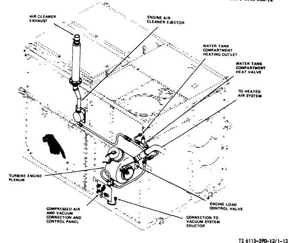
Figure 1-13. Compressed Air System. (TS 6115-590-12/1-13).
(12)
Four conditioned air duct clamp assemblies
used to join the air conditioning duct assemblies
together as required for additional length.
(13)
One divider panel to separate the conditioned
air outlet compartment.
(14)
One vacuum hose assembly for connection of
the power plant vacuum system to other elements of the
MUST hospital that require vacuum service
(15)
One external fuel filter/separator assembly for
filtering inlet fuel to the power plant.
(16)
One fuel hose assembly for connecting the
fuel outlet of the filter/separator to the power plant.
(17)
One fuel hose assembly for connecting the
fuel source to fuel inlet of the filter/separator.
(18)
One fuel hose assembly for extending the
inlet hose from the fuel source to the filter/separator.
(19)
One water recirculating hose to permit the
circulation of water to prevent freezing.
(20)
One cable adapter for connecting two standby
cables together to gain added length when required.
(21)
One ground rod for connecting the power
plant to earth ground.
(22)
One anti-icing hose for the engine air filter de-
icer. (See item 7 of fig. 1-15, sheet 3 of 7).
1-6. Differences Between Models.
This manual covers Power Plant, Utility, Gas Turbine
Engine Driven, AiResearch Co. Model PPU85-5, Libby
Welding Co. Model LPU-7, Amertech Corp. Model
APP-1, and Hollingsworth Model JHTW10/96. This
manual reflects the configuration of the Hollingsworth
Model. PIP-1-80-08-007 is to be installed on the
AiResearch Model, the Libby Welding Model, and the
Amertech Model which will bring these models (except
for
minor
differences),
up
to
the
Hollingsworth
configuration. The Hollingsworth power plant has a
different source of supply for the evaporator and
condenser fan motors, heat control valves for heating
(air conditioning), and for the water pumps.
Change 6
1-21