TM 5-6115-590-12
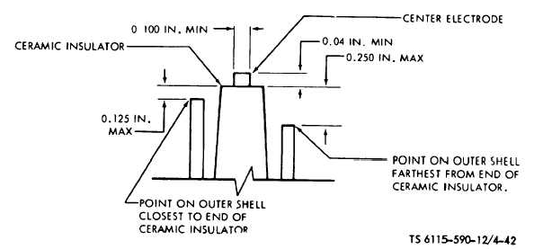
Figure 4-42. Igniter Plug Erosion Limits (TS 6115-590-12/4-42).
(2)
Cleaning and Inspection.
(a)
Clean
relay
with
filtered
compressed air or wipe with a clean rag moistened with
an approved cleaning solvent.
(b)
Visually inspect relay for corrosion,
cracks, damaged threads or other evidence of damage.
(3)
Installation. Install in reverse order of
removal procedure.
j.
Relay (K15).
(1)
Removal. Tag and disconnect electrical
connections to relay (fig. 4-37). Remove four nuts, eight
flat washers, eight lock washers, and four screws.
Remove relay.
(2)
Cleaning and Inspection.
(a)
Clean
relay
with
filtered
compressed air or wipe with a clean rag moistened with
an approved cleaning solvent.
(b)
Visually inspect relay for corrosion,
cracks, damaged threads or other evidence of damage.
(3)
Installation. Install replacement relay in
reverse order of installation.
k.
Current Transformer 400.Hz CT1, CT2, CT3 (fig.
4-37).
(1)
Removal. Tag and disconnect electrical
connections to transformer and electrical leads passing
through the center of the transformer. Remove four
attaching screws and washers and remove transformer
from power chassis.
(2)
Cleaning and Inspection.
(a)
Clean
transformer
with
filtered
compressed air or wipe with a clean rag moistened with
an approved cleaning solvent.
(b)
Visually
inspect
transformer
for
corrosion, cracks, damaged threads, excessive heat or
other evidence of damage.
(3)
Installation.
Install
replacement
transformer in reverse order of removal.
l.
Thermal Relay (three used: S10-A, S10-B, S10-
C) (fig. 4-38).
(1)
Removal. Remove two screws and cover
from relay. Tag and remove electrical leads and bus
bars from relay. Remove two screws, two flat washers
and two lock washers from relay. Remove thermal
relay.
(2)
Cleaning and Inspection.
(a)
Clean relay with compressed air or
wipe with a clean rag moistened with an approved
cleaning solvent.
(b)
Visually inspect relay for corrosion,
cracks, damaged threads, excessive heat or other
evidence of damage.
(3)
Installation. Install replacement relay in
reverse order of removal procedures. m. Shunt R1.
(1)
Removal. Tag and remove electrical
leads from shunt (fig. 4-37). Remove two (2) attaching
screws and washers and remove shunt from power
chassis.
(2)
Cleaning and Inspection.
(a)
Clean
shunt
with
filtered
compressed air or wipe with a clean rag moistened with
an approved cleaning solvent.
(b)
Visually inspect shunt for corrosion,
cracks, damaged threads or other evidence of damage.
(3)
Installation. Install replacement shunt in
reverse order of removal.
n.
Terminal Boards TB5 and TB6 (fig. 4-38 and
4-39).
(1)
Removal. Remove snap on cover from
terminal board. Tag and remove electrical connections
and bus bars from terminal board. Remove
4-92