TM 5-6115-590-12
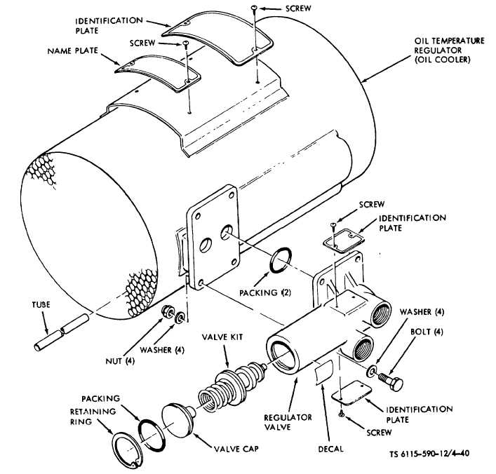
Figure 4-40. Oil Cooler and Regulator Assembly (TS 6115-590-12/4-40)
(4)
Installation. Install replacement protective
panel in reverse order of removal.
h.
Relay (K10).
(1)
Removal. Tag and disconnect electrical
connections to relay (fig. 4-37). Remove four screws,
four flat washers, and four lock washers. Remove relay.
(2)
Cleaning and Inspection.
(a)
Clean
relay
with
filtered
compressed air or wipe with a clean rag moistened with
an approved cleaning solvent.
(b)
Visually inspect relay for corrosion,
cracks, damaged threads or other evidence of damage.
(3)
Installation. Install in reverse order of
removal procedures.
i.
Relay (K12).
(1)
Removal. Tag and disconnect electrical
connections to relay (fig. 4-38). Remove four screws,
four flat washers, and four lock washers. Remove relay.
4-90

