TM 5-6115-590-12
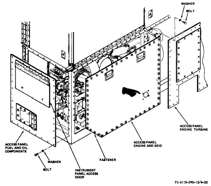
Figure 4-32. Engine and Skid Access Panel Removal (TS 6115-59012/4-32)
Some components of the engine and skid assembly
(bleed load control valve, air pressure regulator and
load control thermostat) are vital components of the
bleed air, exhaust and heating installation, and a such
are covered in Section XI.
4.52. Fuel Boost Pump
a.
Removal (fig. 4-38).
(1)
Remove wiring harness connector and
tube assembly from fuel boost pump.
(2)
Remove four attaching bolts, (fig. 4-34)
eight washers and four nuts. Remove fuel boost pump
from skid assembly.
b.
Installation.
(1)
Install
replacement
pump
on
skid
assembly and secure with attaching bolts, washers and
nuts.
(2)
Connect tube assemblies to pump using
new packings. Connect wiring harness connector to
pump.
4-53. Fuel Float Tank Assembly and Switch
a.
General. The fuel float tank (fig. 4-34) is
equipped with a fluid limit switch which automatically
shuts down the power unit in the event that no fuel is
transmitted to the fuel float tank. This safety feature is
designed so that the fuel control will not be allowed to
run dry and subsequently malfunction.
b.
Removal.
(1)
Remove plug and drain fuel tank.
(2)
Remove tube assemblies and wiring
harness connector from fuel float tank.
(3)
Remove two attaching nuts, washers and
bolts and remove fuel float tank from skid assembly.
Change 6 4-79


