TM 5-6115-590-12
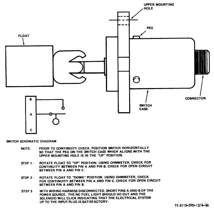
Figure 4-36. Fuel Float Tank Switch Test (TS 6115-590-12/4-36)
(2)
Disconnect tube assemblies (fig. 4-34)
and loosen clamps and slide from each end of fuel tank.
Remove fuel tank from skid assembly.
b.
Installation.
(1)
Install fuel tank assembly in reverse or
removal. Secure with clamps.
(2)
Reconnect tube assemblies.
4-57. Electrical
Electrical
components
on
the
engine
skid
assembly consists of the upper and lower electrical
power chassis, their components, generators, and wiring
harnesses.
4-58. Upper Electrical Power Chassis Assembly
a.
General. The upper electrical power chassis
assembly consists of the 60 and 400 Hz voltage
regulators, battery charger assembly, protective panels
and electrical harness assembly. This paragraph
describes
procedure
for
maintaining
the
chassis
assembly.
Access
to
the
chassis
assembly
is
4-83

