TM 5-6115-590-12
Figure 4-35. Fuel Float Tank Assembly and Fluid Control Limit Switch (TS 6115-590-12/4-35).
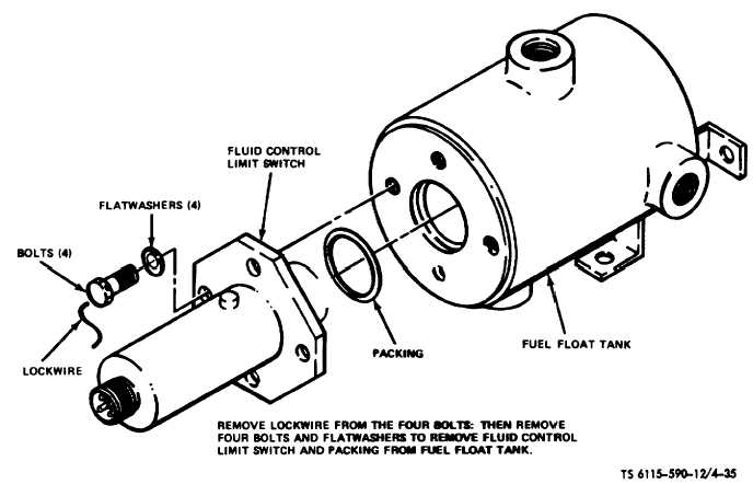
c.
Disassembly. Disassemble fuel float tank and
fluid limit switch in accordance with the instructions
contained in figure 4-35.
d.
Cleaning, Inspection and Repair.
(1)
Clean all non-electrical parts with an
approved cleaning solvent and dry thoroughly with
filtered compressed air.
(2)
Inspect hardware for stripping, cross-
threading, or other damage.
(3)
Inspect tank for cracks, dents or other
damage.
(4)
Inspect switch for external damage.
(5)
Replace packing each time tank assembly
is disassembled.
(6)
Replace damaged or inoperative switch.
(7)
If tank is damaged beyond-repair, replace
it.
(8)
Use new hardware as required.
e.
Fluid Control Limit Switch Test. Test the fluid
control limit switch in accordance with the procedures
given on figure 4-36.
f.
Reassembly. Reassemble switch and tank in
reverse order of disassembly as shown on figure 4-35.
g.
Installation.
(1)
Install replacement fuel float tank in
reverse order of removal.
(2)
Install plug in bottom of fuel tank.
4-54. Fuel Float Tank Vent Valve
a.
Removal.
(1)
Remove the two tube assemblies (fig.
4-34) and elbows from vent valve.
(2)
Remove two screws and washers and
remove valve from mounting bracket.
b.
Installation.
(1)
Install replacement valve in reverse order
of removal.
(2)
Install
elbows
and
connect
tube
assemblies.
4-55. Oil Tank Assembly
a.
Removal. Drain all oil from tank assembly (fig.
4-33). Remove tube assemblies from oil tank, loosen
clamp strap on tank cradle, and remove oil tank
assembly from cradle.
b.
Installation.
Install
replacement
oil
tank
assembly in place of cradle and secure with a clamp
strap. Reconnect tube assemblies to tank using new
gaskets. Insure that drain plug is securely tightened.
Refill oil tank.
4-56. Fuel Tank Assembly
a.
Removal
(1)
Remove drain plug from fuel tank (fig.
4-33) and allow all fuel to drain from tank.
4-82