
TB 9-6625-2252-35
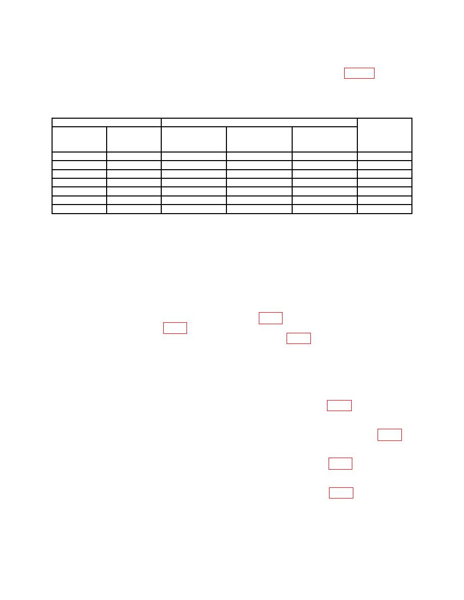
(4) Repeat technique of (1) through (3) above using settings listed in table 5. If
calibrator does not indicate within limits specified, perform appropriate adjustment
as listed.
Test instrument
Calibrator settings and indications
RANGE
switch
Decade dial
settings
settings
Min
Max
Adjustments
1
1.0000
20 kHz
0.998
V
1.002
V
b(7)
10
10.000
200 Hz
9.98
V
10.02
V
b(8)
10
10.000
20 kHz
9.98
V
10.02
V
b(9)
100
100.00
200 Hz
99.8
V
100.2
V
b(10)
100
100.00
20 kHz
99.8
V
100.2
V
b(11)
1000
1000.0
200 Hz
998
V
1002
V
b(12)
1000
1000.0
20 kHz
998
V
1002
V
b(13)
b. Adjustments
NOTE
Use insulated screwdriver when performing adjustments.
(1) Set NULL SENS switch to TVM and disconnect calibrator from TI.
(2) Short TI INPUT HI and LOW.
(3) Connect multimeter INPUT HI to A3TP1 (fig. 1) and LO to A2 terminal 2.
Adjust A3R3 OFFSET ADJ. (fig. 1) until multimeter indicates between 2.4 and 2.6 V dc
when adjustment tool is removed from A3R3 OFFSET ADJ. (fig. 1).
(4) Disconnect multimeter and remove short from TI INPUT HI and LOW.
(5) Connect calibrator OUTPUT HI and LO to TI INPUT HI and LOW.
(6) Set calibrator for a 1 V, 200 Hz output. Set NULL SENS switch to each
successively more sensitive position and adjust A3R6 LOW FREQ CAL (fig. 1) until TI
indicates a null (R). Repeat a l) through (3) above.
(7) Set calibrator for a 1 V, 20 kHz output. Adjust A3C3 HIGH FREQ. CAL (fig. 1)
until TI indicates a null (R).
(8) Set calibrator for a 10 V, 200 Hz output. Adjust A12R1 10V (fig. 1) until TI
indicates a null (R).
(9) Set calibrator for a 10 V, 20 kHz output. Adjust A13C1 10V (fig. 1) until TI
indicates a null (R).
8
