
TB 9-6625-2182-35
(c) Press TI ENTRY FM pushbutton and enter DATA frequency modulation
as listed.
(d) Using measuring receiver, measure FM deviation. Measuring receiver
deviation will indicate within limits specified in table 19.
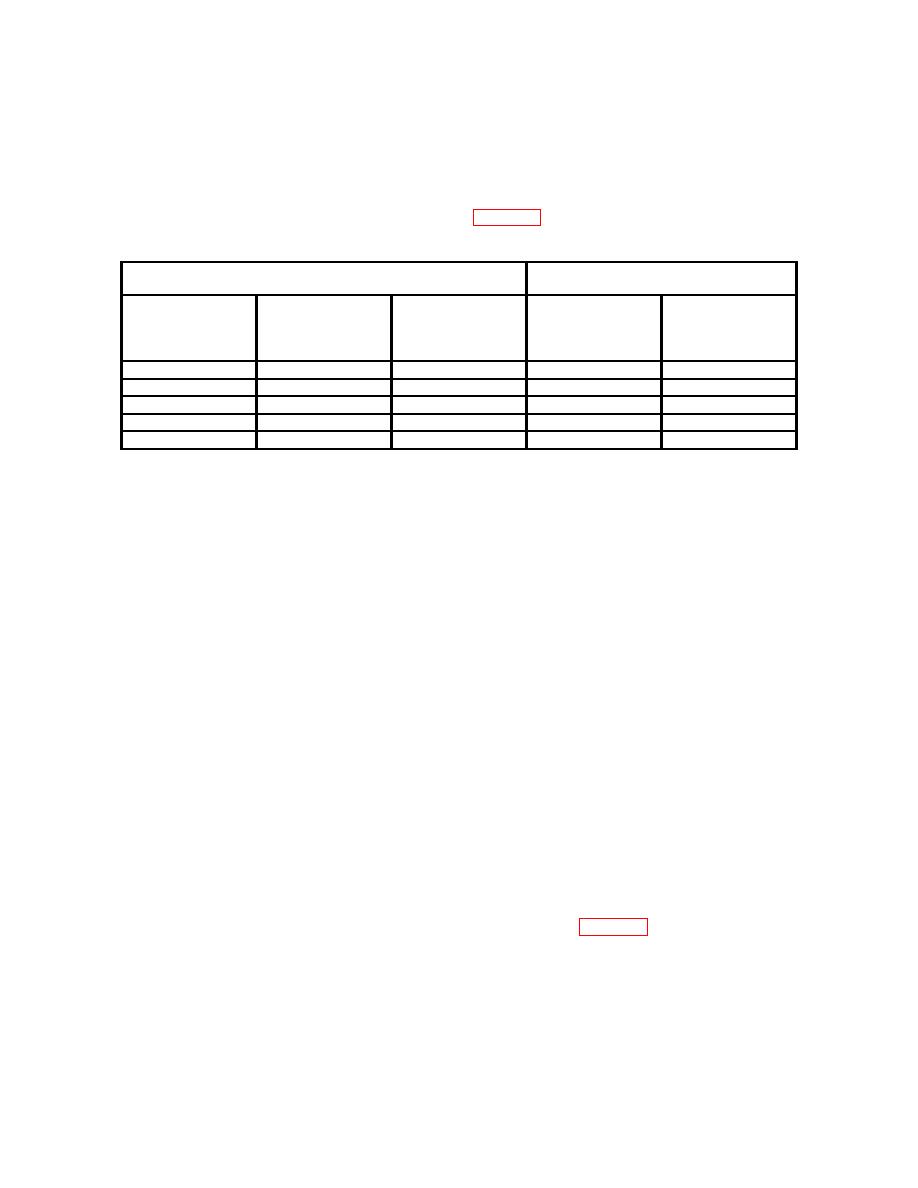
Table 19. FM Deviation
Modulation analyzer indications
Test instrument
(kHz deviations)
DATA
DATA frequency
modulation
DATA carrier
modulation (FM)
frequency
frequency
(kHz)
(kHz)
(MHz)
Max
Min
1050
100
100
95
105
256
100
25
23.7
26.3
256
100
187
177.6
196.4
256
100
375
356.2
393.8
50
10
150
142.5
157.5
b. Adjustments. No adjustments can be made.
17. Phase Modulation
a. Performance Check
(1) Set measuring receiver to measure FM with a 300 Hz high pass filter and
a 15 kHz low pass filter.
(2) Set audio analyzer to measure distortion.
(3) Press TI pushbuttons as listed in (a) through (k) below:
(a)
INSTR PRESET.
(b)
ENTRY - AMPTD.
(c)
DATA - (+10 dBm).
(d)
SHIFT.
ENTRY - ΦM.
(e)
(f)
MODULATION SOURCE - EXT DC.
(g)
ENTRY - MOD FREQ.
(h)
DATA - 1 kHz.
(i)
SHIFT.
(j)
ENTRY- MOD OUT.
(k)
DATA - (+1 V).
(4) Perform steps (a) through (c) below for each row in table 20.
(a) Press ENTRY FREQ and enter DATA carrier frequency.
(b) Press SHIFT - ΦM and enter DATA rad.
(c) Set the measuring receiver to measure the PM. Phase modulation will
indicate within limits specified.

