TM 55-2835-209-23
4-15 REPLACE FUEL SOLENOID VALVE (CONT)
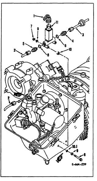
INSTALLATION
1.
2.
3.
4.
5.
6.
7.
8.
9.
NOTE
As all tubes and connectors
are installed/connected, all
protective caps/plugs shall be
r e m o v e d .
Lubricate packings (6) with lubri-
cant (D19) and install new packings
(6) on reducer (4) and union (5).
Install reducer (4) and union (5).
Torque to 60 to 65 inch-pounds.
Position fuel solenoid valve (11)
in-line with tube (2) on fuel sole-
noid valve inlet side.
Be sure flow
arrow on fuel solenoid valve is
pointing aft.
Connect tubes (2, 3) to reducer (4)
and union (5).
Secure fuel solenoid valve (11) with
washers (9), bolts (8), nuts (7),
spacers (10) and packings with re-
tainer (10.1).
Torque nuts to 28 to
32 inch-pounds.
Torque tube (2) to 100 to 120 inch-
pounds.
Torque tube (3) to 70 to 80
inch-pounds.
Install electrical connector (1).
Lockwire electrical connector using
lockwire (D43).
Perform leak check.
Install fuel control upper cover
(Task 4-10).
FOLLOW-ON MAINTENANCE: MOC required.
Change 1
4-43