TM 55-2835-208-23
2-100.3 INSTALL OIL FILLER TUBE AND DIPSTICK ASSEMBLY
2-100.3
INITIAL SETUP
Applicable Configurations:
APU 116305-300
APU 116305-302
Tools:
Engine Repairman’s Tool Kit
NSN 5180-00-323-4944
Torque Wrench
NSN 5120-00-542-4489
Materials:
Assembly Fluid No. 1 (E31)
Personnel Required:
68B Aircraft Powerplant Repairer
68B Powerplant Inspector
References:
TM 55-2835-208-23P
Equipment Condition:
APU in Assembly Fixture (Task 1-22)
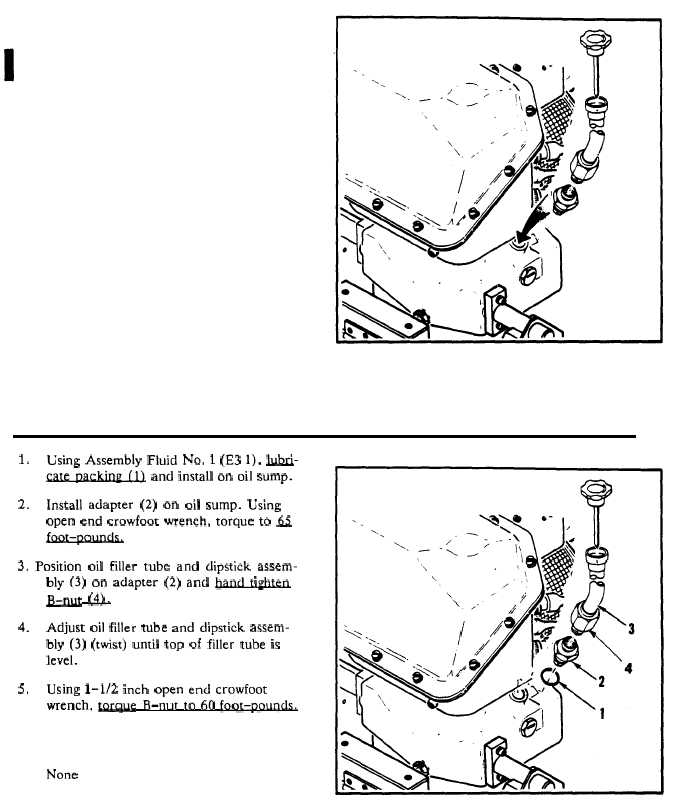
1.
Using Assembly Fluid No. 1 (E3 1), l.ulxi-
~ and install on oil sump.
2.
Install adapter (2) on oil sump. Using
open end crowfoot wrench, torque to h
3. Position oil filler tube and dipstick assem-
bly (3) on adapter (2) and ~
“o
B-nut (4?.
4.
Adjust oil filler tube and dipstick assem-
bly (3) (twist) until top of filler tube is
level.
5.
Using 1-1/2 inch open end crowfoot
wrench, -e B-nut to 60 foot-po-
INSPECT
FOLLOW ON MAINTENANCE:
None
END OF TASK
Change 5
2-182.3