
TM 1-2840-252-23-2
4-75 ASSEMBLE TAILPIPE ASSEMBLY (Continued)
4-75
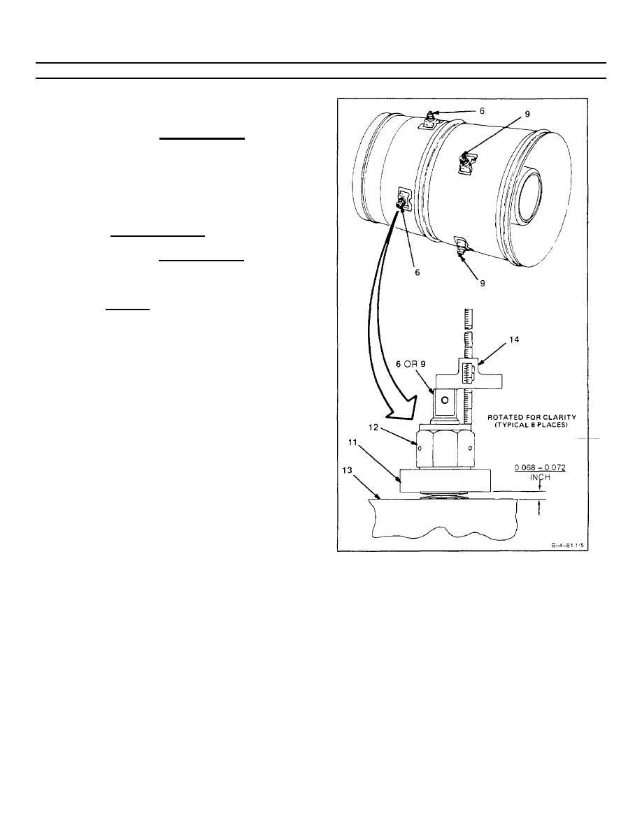
10. Tighten nut (12) at each end of support rods (6 and
9) Dimension between spacer (11) and tailcone
bracket (13) shall be 0.068 - 0.072 inch.
NOTE
In the following step 11., protrusion measurement
shall be from end of support rod to top of nut.
In order to achieve the requirements of step 11,
dimension 0.068 - 0.072 inch may vary beyond
limits provided the sum total of gap (two places) on
each individual rod is 0.122 - 0.164 inch.
11. Using a depth vernier (14) measure protrusion of
support rods (6 and 9). Protrusion at one end shall
be within 0.06 inch of protrusion measured at opposite
end.
12. If protrusion measured in step 11 is not within
tolerance for any support rod (6 or 9), perform the
following.
a.
Loosen nut (12) at each end of support rod.
b.
Center support rod.
c.
Repeat steps 10 and 11.
13. Lockwire nut (12) to rod end. Use safety cable (E49).
INSPECT
FOLLOW-ON MAINTENANCE
None
END OF TASK
4-429
