
TM 1-2840-252-23-2
4-58
REMOVE SECOND TURBINE NOZZLE, SPACER, CASE, AND BUMPER
4-58
(AVIM) (Continued)
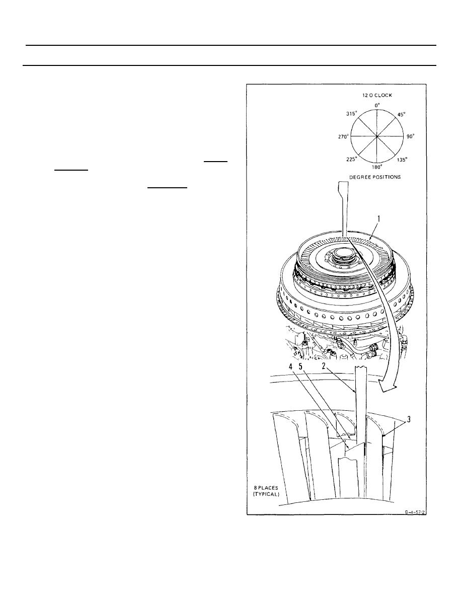
1. Measure first turbine disc assembly (1) tip
clearance at 0, 45, 90, 135, 180, 225, 270, and 315
degree positions as follows:
a. Insert thickness gage (Appendix E) (2) between
second turbine nozzle vanes (3) and between
blade tip (4) and turbine rotor case inside diameter
(5).
b. Rotate first turbine disc assembly
(1)
one
revolution for each measurement.
c. Tip clearance shall be 0.019 inch minimum.
Record positions below minimum.
INSPECT
GO TO NEXT PAGE
4-314
