
TM 1-2840-252-23-2
4-40
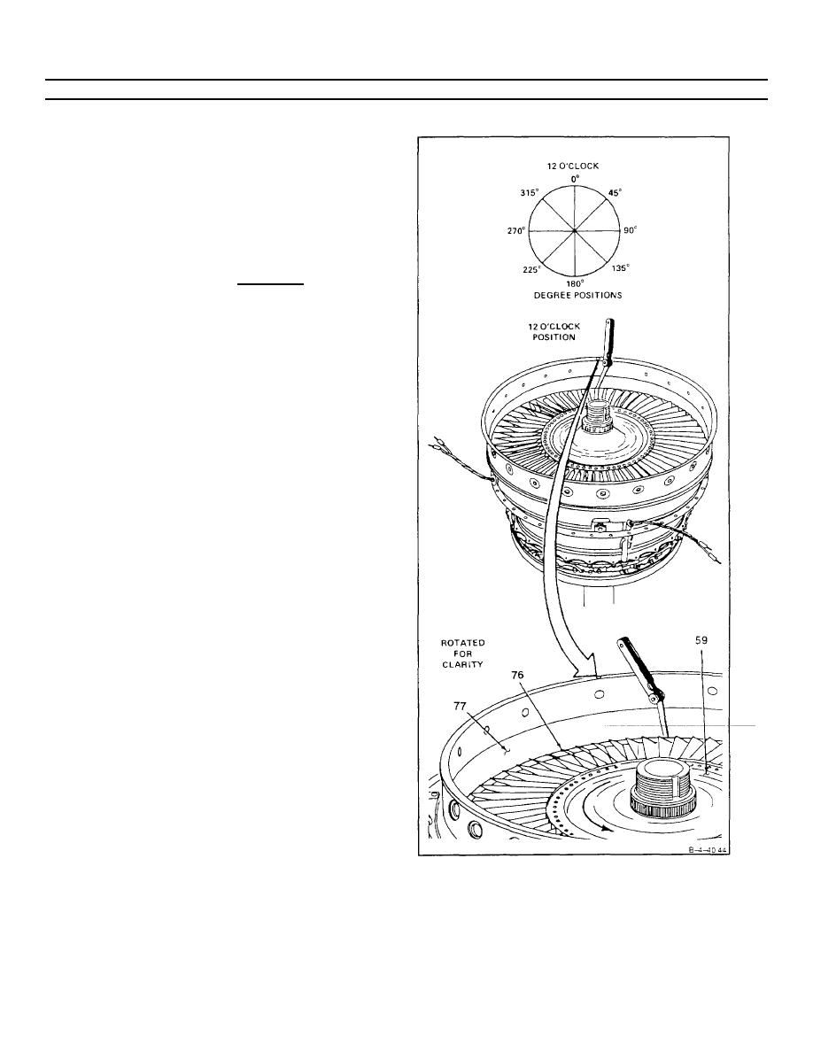
INSTALL NO. 4 AND 5 BEARING PACKAGE SEALS (AVIM) (Continued)
4-40
Measure clearance between tips of blades (76)
42.
and fourth stage power turbine nozzle (77) (tip
clearance) at 0, 45, 90, 135, 180, 225, 270, and
315-degree positions as follows
a. Insert thickness gage between fourth stage
power turbine nozzle (77) and blade (76) tip
Rotate fourth stage turbine rotor (61 ) counter-
clockwise one revolution for each check
b. Tip clearance shall be 0.020 inch minimum
GO TO NEXT PAGE
4-209
