
TM 55-2840-254-23
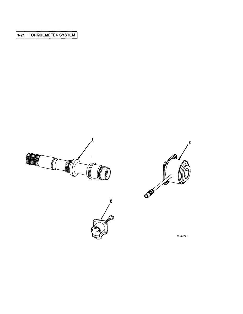
Provides means to monitor engine power output. (Ref. Appendix D.) Needs electrical input signal from air-
frame supplied power supply. Creates electrical signal in direct proportion to the amount of torque devel-
oped. Electrical signals averaged and directed to cockpit indicator. Engine parts are a calibrated set. One
defective part means all three must be replaced. Engine parts are listed and keyed in following diagram.
A.
OUTPUT SHAFT. Located at front of engine within inlet housing assembly. Main torque
system component; also major engine component. Splines directly to power shaft,
and provides internal splines for helicopter drive shaft. Rotates within head assem
bly. As torque is applied to shaft, voltages are induced into head assembly coils.
HEAD ASSEMBLY. Located within inlet housing assembly and encircles part of output shaft.
B.
Transformer containing three primary coils and six secondary coils. Electrical
connector provided. Transfers induced voltages to junction box.
JUNCTION BOX. Externally mounted at 3-o'clock position on inlet housing assembly. Connects
C.
electrically to head assembly. Converts AC voltage signals to DC signals. Provides ex-
ternal connector to transfer electrical signals to cockpit indicator.
