TM 55-2840-254-23
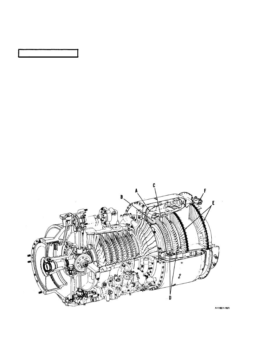
1-16 TURBINE SECTION
Directs and uses energy created in combustion section to keep compressor rotor turning and for output
power. Includes gas producer and power turbine components. Contains provisions for measuring gas
temperature at input to power turbine assembly. Also contains provisions to contain engine parts in case
of internal engine failure.
A
CURL ASSEMBLY. Located directly behind air diffuser. Forms outer wall of path for hot gases
leaving combustion section. Smoothly changes direction of hot gases and guides
them to first gas producer nozzle.
B
FIRST GAS PRODUCER NOZZLE. Located aft of curl assembly and forward of first gas producer
disc assembly. Outer portion forms inner walI of path for hot gases leaving combus-
tion section. Nozzle vanes direct hot gases so they hit first gas producer disc blades
most efficiently.
C
SECOND GAS PRODUCER NOZZLE. Located between first and second gas producer disc assem-
blies. Nozzle vanes direct hot gases leaving first gas producer disc assembly so they
hit second gas producer disc blades most efficiently.
D
GAS PRODUCER DISC ASSEMBLIES. Coupled directly to compressor rotor assembly. As hot gases
hit disc assembly blades, disc assemblies turn causing compressor rotor to turn.
E
POWER TURBINE ASSEMBLY. Contains two disc assemblies, two nozzles, No. 4 and 5 bearing
package and a thermocouple system (see G through L).
F
TURBINE EXIT VANE. Mounts on rear of engine. Distributes exhaust to lower the effect of thrust.
Also, helps to prevent engine parts from being thrown about should damage occur
internally in power turbine assembly.
1-20


