ARMY
TM 5-6115-612-34
NAVY AG-320B0-MME-00
8-4. OVERHAUL OF TURBINE ASSEMBLY.
(cont)
f.
Reassembly. (cont)
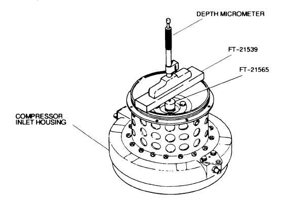
(28) Place fabricated tool (FT-21565, Figure 8-
16) on top of turbine shaft Place fabricated tool (FT-
21539) on top of compressor inlet housing Center hole
over fabricated tool (FT-2156) Take a base reading from
the top of shaft to top of fabricated tool (FT-21539) using
depth micrometer Note the reading. The shaft must be
stretched 0.007- 0.009 inch (0.018-0.023 cm) from the
original reading.
(29) Tighten nut and remeasure shaft length
Repeat procedure until 0.007-0.009 inch (0.018-0.023
cm) stretch has been achieved
CAUTION
Be sure all grinding dust, chips, and
burrs created by balancing operations
are
removed
before
each
step
of
assembly. Failure to remove dust,
chips, and burrs will create excessive
runout when parts are assembled and
may lead to rotating group damage
during engine operation.
(30) Install assembly in bench center On two
center points, maintain runout at 0 002 inch (0 005 cm)
at point K, Figure 8-13
Figure 8-16. Obtaining Reading for Turbine Wheel Shaft Stretch for Final Assembly
Using Fabricated Tools FT-21539 and FT-21565
Change 4 8-39