ARMY
TM 5-6115-612-34
NAVY
AG-320B0-MME-00
84.
OVERHAUL OF TURBINE ASSEMBLY.
(cont)
f.
Reassembly (cont)
(9)
Use wire gage and check clearance
between compressor wheel blade tips and inlet housing.
Adjust shim set (step (5) above) as necessary to attain
clearance of 0 014-0 016 inch (0 036-0 041 cm)
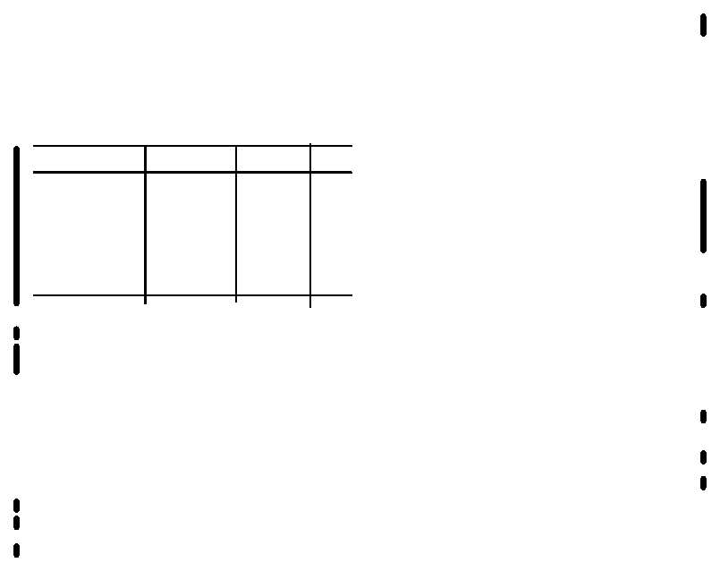
Type of
Thickness
Part No
Qty
Shim/Washer
Bearing Shim
0 024 Inch
101444-1
Metallic Shim
0 002 Inch
101414-4
4 ea
Metallic Shim
0 005 Inch
101414-5
3 ea
Metallic Shim
0 020 Inch
101414-6
2 ea
Wave Washer
101437-1
(10) When
correct
clearance
is
attained,
install
production bearing (37, Figure 8-6) in step (1) Repeat
steps (2) and (3) Ensure that bearing retainer nut (40) is
positioned to allow tabs of tab washer (38) to be bent
Repeat steps (4) thru (5) Install preformed packing (39).
Coat outside diameter of bearing housing at packing and
mating surface of compressor inlet housing with
petrolatum, VV-P-236
CAUTION
DO NOT bend tabs on washers (35)
(11) Using jackscrews as a guide and to keep
shims in place, place correct shim stack (37) and bearing
housing (36) in compressor inlet housing (3). Secure
with washers (35) and bolts (34). Torque bolts to 70-88
inch pounds (7.91-9 04 Nm). Bend tabs on tab washer
(38). Lockwire using MS20995-C32 lockwire.
(12) Install labyrinth seal (29) on back of
compressor wheel (33)
WARNING
To prevent injury, ensure that insulated
gloves are worn when handling dry Ice
and cold parts
CAUTION
To prevent engine failure, ensure that retaining ring (30)
that secures oil passage plug (31) is correctly Installed
(13) Install preformed packing (32) on oil
passage plug (31) Secure in place in diffuser (2) with
retaining ring (30) Ensure that retaining ring is under
retaining groove
CAUTION
If diffuser (2) drops into place without heating and
cooling, replace diffuser
(14) Place diffuser (2) In solution of dry ice and
alcohol for approximately 15 minutes. Use soft flame
and heat outside of inlet housing.
(15) Remove diffuser from solution and Install in
compressor inlet housing (3) Ensure that oil tube holes
and bolt holes are alined.
(16) Install bolts (13) in the 1, 4, 7, 10, 13, and
16 positions. (See Figure 8-7.) Secure with washers (11
and 12, Figure 8-6) and nuts (10). Torque to 74-79 Inch
pounds (8.36-8.93 Nm)
8-36 Change 4


