A R M Y
TM 5-6115-612-12
MARINE CORPS TM 6115-12/7
AIR FORCE
TO 35C2-3-471-1
N A V Y
AG-320B0-0MM-000
4-83. MAGNETIC CONTACTOR. (cont)
b. Test. (cont)
(6) Tag and disconnect wiring.
perform continuity check on output
contactor.
If shorts and opens are
present, replace output contactor.
(7) Install air baffle (paragraph
4 - 2 2 ) .
(8) Install engine housing access
cover
and
secure
with
turnlock
fasteners.
(9) Close
and
securely
latch
Inlet air housing access door.
(10) Connect battery cable plug
connector.
(11) Stow power cable on cable
c.
Removal.
Refer to figure 4-51.
(1) Remove
component
mounting
panel (paragraph 4-82).
(2) Tag and disconnect all wiring
from output contactor (6).
(3) Disconnect conductor bus (1)
from current shunt (2).
(4) Remove nuts (3), washers (4),
and self-locking nuts (5) that secure
contactor to component mounting panel.
d. Installation.
(1) Place contactor (6) in posi-
tion on
component
mounting panel.
Secure with screws (5), washers (4),
and nuts (3).
Torque to 32-35 inch
pounds (3.6-3.9 Nm).
support.
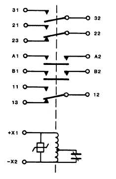
Figure 4-50.
Magnetic Contactor Schematic (Off Position)
4-152


