TM 5-6115-590-12
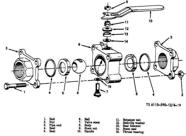
Figure 4-19. Inlet and outlet values, filter/separator (TS 6115-590-12/4-19).
(c)
K6 UNDERFREQUENCY lamp illuminated.
(d)
K7 400 Hz CONTROL lamp illuminated.
(e)
K8 60 Hz CONTROL lamp illuminated.
(8)
With the engine operating at governed speed,
momentarily actuate the EMERGENCY OPERATION switch
on power unit instrument panel to ON position. This is a
check on the 400 Hz output contactor (K12). Observe that the
following occurs on the analyzer panel.
(a)
K12 400 Hz OUTPUT CONTACTOR lamp
illuminates.
(b)
K7 400 Hz CONTROL lamp is extinguished.
(c)
K8 60 Hz CONTROL lamp is extinguished.
(9)
The 400 Hz OUTPUT CONTACTOR (K12) may be
checked by an alternate method. Place 400 Hz system main
contactor switch and output contact switch on power unit
instrument panel in CLOSE position. Observe the K12 400
Hz OUTPUT CONTACTOR lamp on the analyzer panel
illuminates.
(10)
Actuate STOP switch on analyzer panel or place
MASTER switch on power unit instrument panel in STOP
position and observe that the engine shuts down.
NOTE
Sequence of events during performance
check, table 4-4, may be utilized during the
functional check procedure to determine the
sequence of events, and as an aid in isolating
failures.
4-32


