
TM 1-2840-252-23-3
G-50
FAULT CODE B5, COLLECTIVE PITCH ANGLE LVDT EXPANDED INSTRUCTIONS
Refer to numbered steps in figure 136.
Step 4.
Check harness connector PL3 (figure 201) at DECU and LVDT connecor for tight connections.
t
Step 5.
Disconnect connector PL3 and LVDT connector to check pins and sockets.
Step 7.
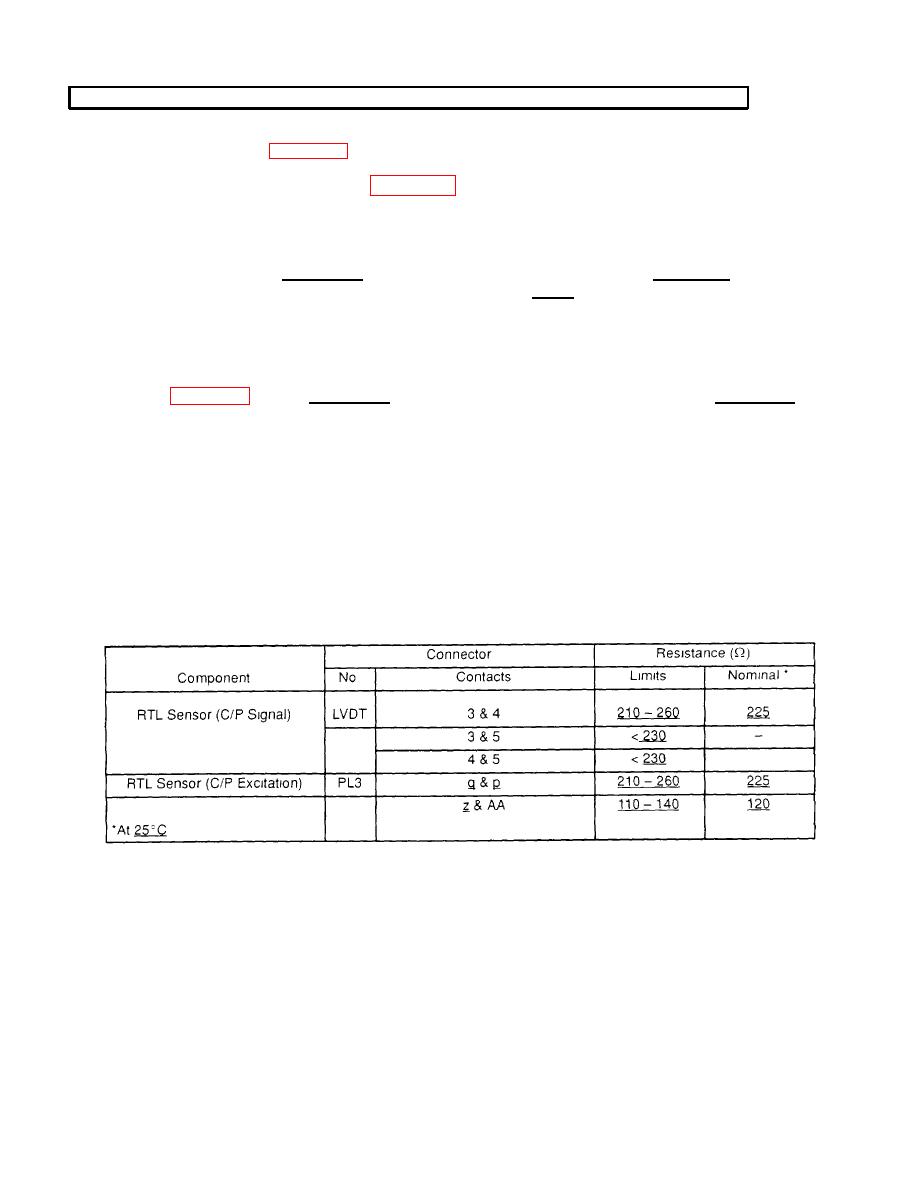
With LVDT connector disconnected, check resistance of RTL sensor at sensor connector pins
1 and 2. Limit is 110 - 140Ω. Check resistance at pins 3 and 4. Limit is 210 -260Ω. Check
resistance at pins 3 and 5, and pins 4 and 5. Limit is < 30Ω.
2
Step 8.
Before tightening harness connector PL3 and LVDT connector, be sure that keyway in harness
connectors are aligned with keyways incomponent connectors.
Step 11.
With PL3 disconnected, check resistance of RTL sensor at harness PL3 connector sockets q and p
Step 12.
Refer to manufacturer's procedure for checking RTL sensor operation.
Step 17.
Refer to manufacturer's procedure for diagnosing and replacing harness or RTL sensor.
Step 19.
Refer to manufacturer's procedure for diagnosing and replacing harness.
Step 21.
Refer to manufacturer's procedure for replacing RTL sensor.
RESISTANCE-CHECK SUMMARY
G-113
