
TM 1-2840-252-23-3
G-49
FAULT CODE B4, T4.5 SENSOR EXPANDED INSTRUCTIONS
Refer to numbered steps in figure 135.
Step 3.
Check harness connector PL3 (figure 201) at DECU, and J19 at T4.5 harness for tight connections.
Step 4.
Disconnect connectors PL3 and J19 to check pins and sockets.
Step 6.
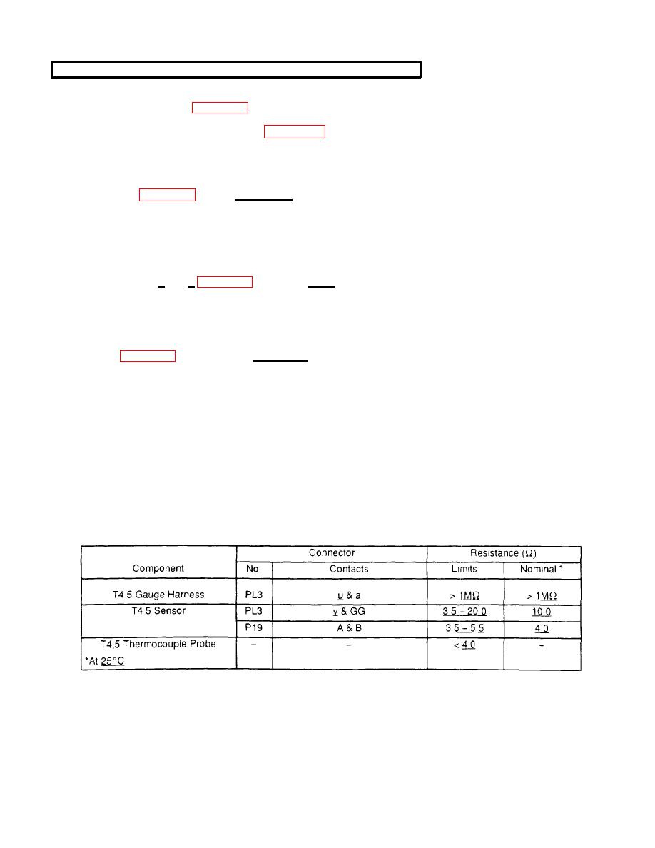
With PL3 disconnected, check resistance of T4.5 sensor at harness PL3 connector sockets v and
GG (figure 202).Limit is 3.5 - 20.0Ω.
Step 7.
To measure resistance of T4.5 thermocouple probe, disconnect one leg of probe from the bus bar.
Measure resistance. Reverse polarity and measure resistance again. Average the two readings to
obtain final results. (Note: An analog ohmmeter is recommended for measuring probe resistance.)
Step 8.
With PL3 and T4.5 gauge disconnected, check resistance of T4.5 haness at harness connector
r
sockets u and a (figure 202). Limit is > 1MΩ.
Step 9.
Before tightening harness connectors PL3 and P19, be sure that keyways in harness connectors
are
aligned with keyways in component connectors.
Step 12.
With J19 .disconnected, check resistance of T4.5 sensor at sensor P19 connector sockets A and B
Limit is 3.5 - 5.5Q.
Step 17.
Refer to manufacturer's procedure for diagnosing and replacing harness.
Step 19.
Refer to manufacturer's procedure for diag osing and replacing harness.
n
Step 20.
Refer to manufacturer's procedure for diagnosing and replacing T4.5 sensor.
Step 23.
Refer to manufacturer's procedure for diagnosing and replacing harness or T4.5 gauge.
Step 24.
Refer to manufacturer's procedure for diagnosing and replacing harness.
RESISTANCE-CHECK SUMMARY
G-110
