
TM 1-2840-252-23-2
4-67 INSTALL FIRST TURBINE DISC ASSEMBLY (AVIM) (Continued)
4-67
f.
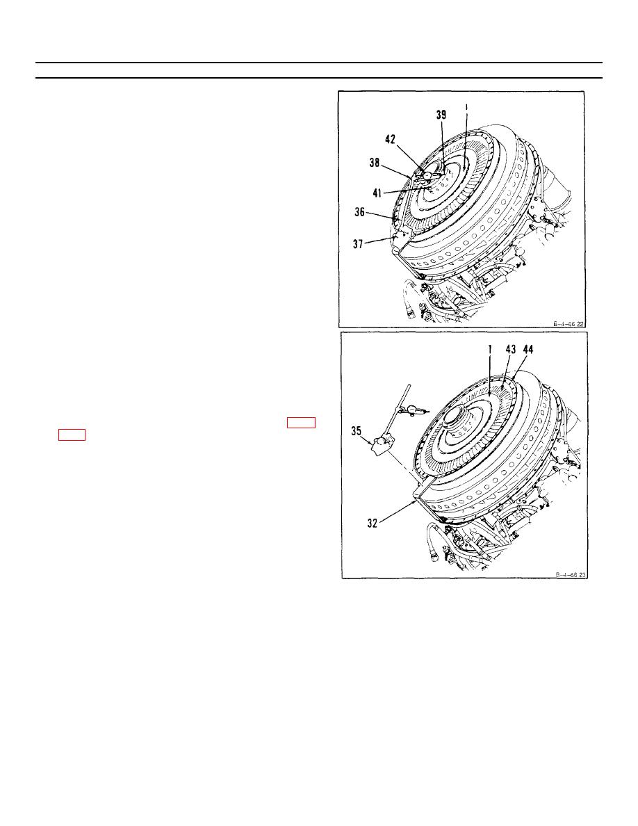
Adjust arm (36) at base (37) and clamp (38).
Position pointer (39) on hub (41).
g.
Zero indicator (42) and rotate first turbine disc
assembly (1). Record dimension. Maximum
allowable runout shall be 0 002 inch.
NOTE
If dimensions recorded in steps 13 e and 13 g are
not within limits do following steps 14 thru 21. If
dimensions recorded in steps 13 e and 13 g are
within limits, omit steps 14 thru 21.
INSPECT
14. Remove dial indicator and base (35) and support
(32).
15. Hold disc assembly (1) steady. Draw a match- mark
on a blade (43) and flange (44) using marking pencil
(E38).
16. Remove first turbine disc assembly (1) (Ref. Task
GO TO NEXT PAGE
4-386
