
TM 1-2840-252-23-2
4-67 INSTALL FIRST TURBINE DISC ASSEMBLY (AVIM) (Continued)
4-67
b.
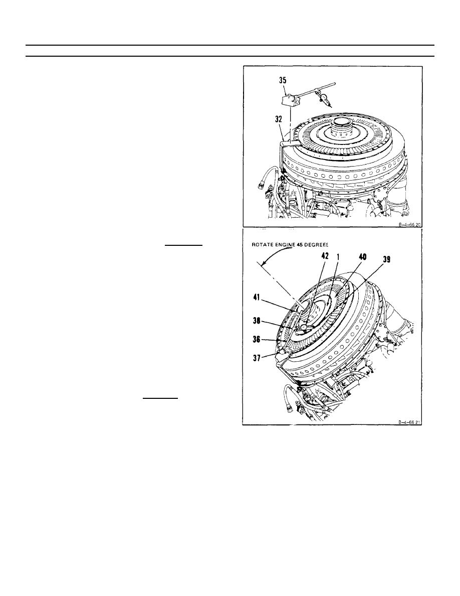
Place dial indicator and base (35) on support
(T40) (32).
c.
Rotate engine to approximately 45 degrees.
NOTE
In following step d, be sure pointer is on disc rim
and not on retaining plate
d.
Adjust arm (36) at base (37) and clamp (38) to
position pointer (39) on outer surface (40)
adjacent to blade roots
NOTE
When checking runout, apply forward pressure to
hub (41) to compensate for bearing internal
clearance.
e.
Zero indicator (42) and rotate first turbine disc
assembly (1) Record dimension.
Maximum
allowable runout shall be 0.004 inch.
GO TO NEXT PAGE
4-385
