
TM 1-2840-252-23-2
4-50
INSTALL FOURTH STAGE POWER TURBINE NOZZLE (AVIM) (Continued)
4-50
c.
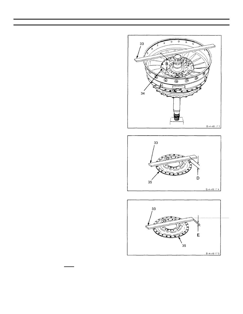
Measure from top of locating bar (T33) (33) to
inner aft face of fourth turbine nozzle assembly
(34), in three locations. Use micrometer depth
gage Record average as dimension B.
d.
Subtract dimension A from dimension B.
Record as dimension C.
e.
Place locating bar (T33) (33) on forward face of
inner bolt circle on heat shield (35).
f.
Measure from top of locating bar (T33) (33) to
forward face of outer flange on heat shield (35)
in three locations. Use micrometer depth gage
Record average as dimension D.
NOTE
In following step g, dimension E is the thickness of
locating bar (T33) (33).
g.
Measure from top of locating bar (T33) (33) to
forward face of inner bolt circle on heat shield
(35). Use micrometer depth gage. Record as
dimension E.
h.
Subtract dimension E from dimension D.
Record as dimension F.
i.
Subtract dimension F recorded in step h from
dimension C recorded in step d to obtain
clearance at inner bolt circle. Record as
dimension G.
NOTE
Clearance required is 0.001 inch minimum.
GO TO NEXT PAGE
4-275
