
TM 1-2840-252-23-2
4-40
INSTALL NO. 4 AND 5 BEARING PACKAGE SEALS (AVIM) (Continued)
4-40
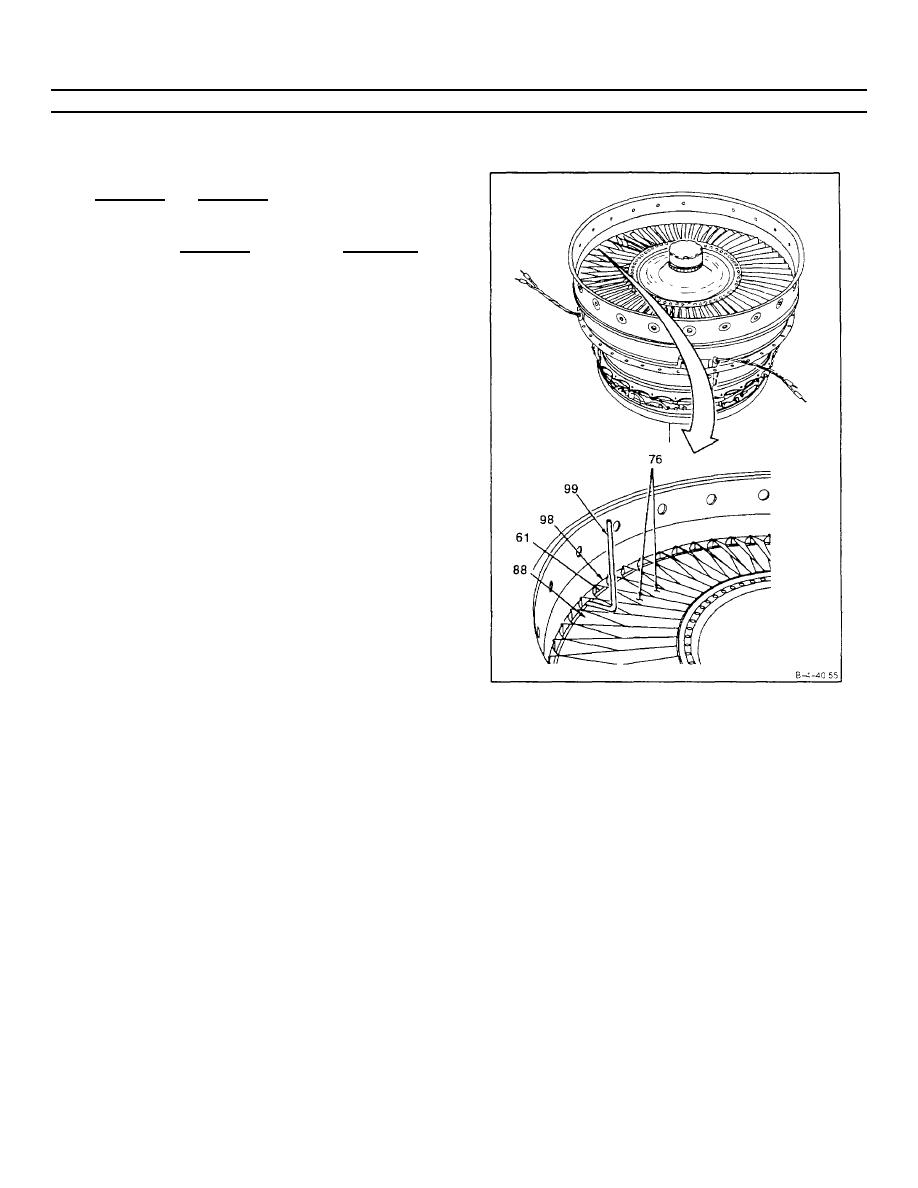
Check axial clearance between fourth stage
50.
power turbine rotor (61) and fourth stage pow-
er turbine nozzle (88) at blade tips (98Use
)
0.115 inch and 0.290 inch bent wire gage (Appen-
dix E) (99) inserted between fourth stage power
turbine rotor blades (76) Axial clearance shall not
be less than 0.115 inch or more than 0.290 inch.
NOTE
If axial clearance is not within limits, do
steps 38 through 50 Ring spacer may be
installed or removed as necessary Re-
check clearance If clearance still is not
within limits, replace power turbine assem-
bly
GO TO NEXT PAGE
4-216
