TB 9-6625-2182-35
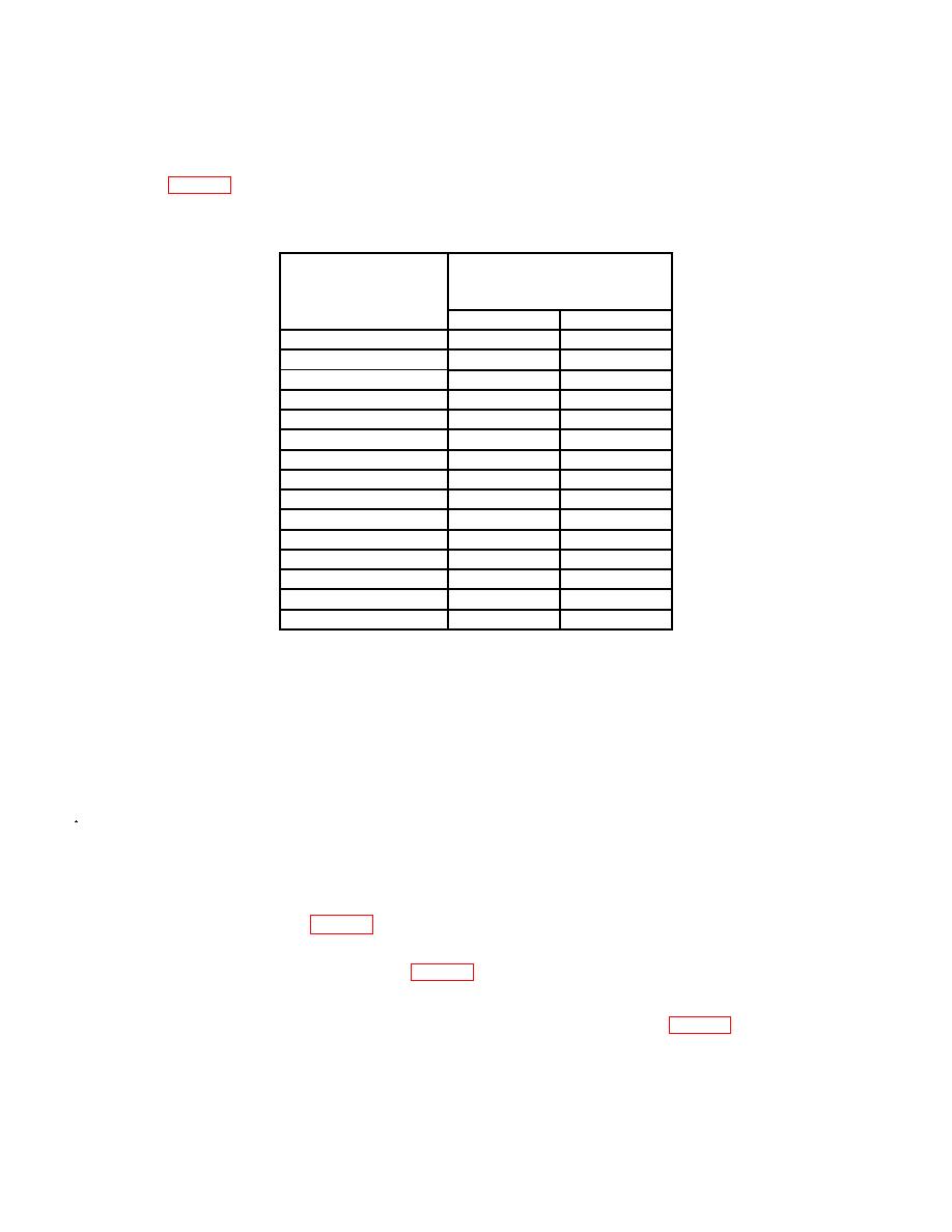
(4) Press TI ENTRY AMPTD pushbutton and enter DATA amplitude for each
row in table 6. Using measuring receiver and RF power measurement techniques,
measured power will indicate within limits specified.
Table 6. RF Output
Measuring receiver
indications
Test instrument
(dBm)
DATA
amplitude
Min
Max
15 dBm
13
17
10 dBm
8
12
5 dBm
3
7
0 dBm
2
-2
1
-10 dBm
-8
-12
-20 dBm
-18
-22
-30 dBm
-28
-32
-40 dBm
-38
-42
-50 dBm
-48
-52
-60 dBm
-58
-62
-70
dBm
-68
-72
-80
dBm
-78
-82
-90
dBm
-88
-92
-100
dBm
-98
-102
-110
dBm
-108
-112
1Setup
measuring receiver for tuned RF level cal techniques and
wait for receiver to calibrate.
(5) Press RF OFF/ON pushbutton to OFF.
b. Adjustments. No adjustments can be made.
a. Performance Check
(1) Set measuring receiver with sensor module to measure RF power in logarithmic
mode, then select the 0.01 dB mode using special function 32.0.
(2) Press pushbuttons ENTRY AMPTD and DATA (+10 dBm).
(3) Measure and record the RF power using the measuring receiver, while using the
ENTRY FREQ key and the DATA key pad to select frequencies between the start and
stop frequencies listed in table 7.
(4) Calculate the flatness using the formula below. The flatness will be less than or
equal to the maximum limits listed in table 7.
Flatness = (highest lowest)/2
(5) Repeat technique of (3) and (4) above for remaining rows in table 7.


