
TM 55-2840-254-23
1-93
1-93 INSPECT ENGINE HOT END (AVIM) (Continued)
24. Install start fuel nozzles (Ref. Task 6-28).
25. Install spark igniters (Ref. Task 7-10).
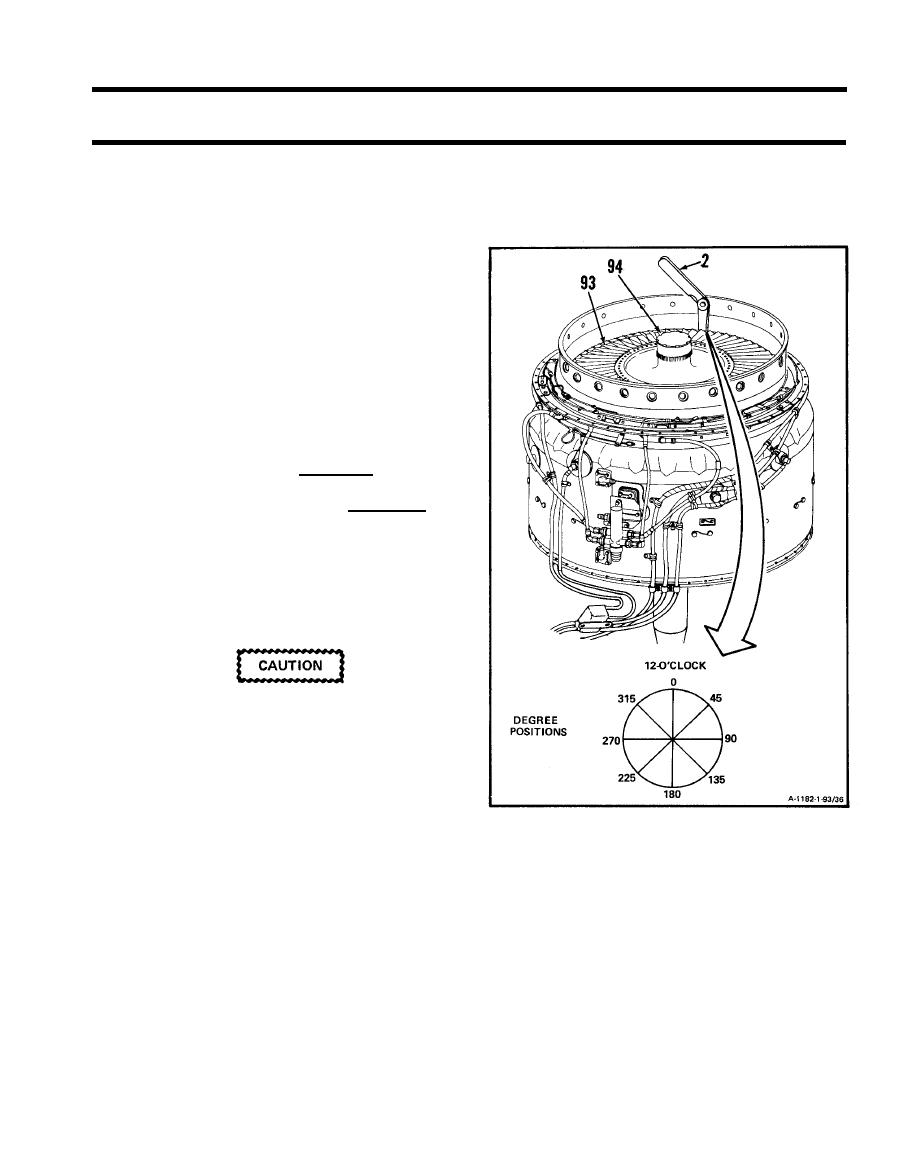
26. Measure fourth stage power turbine rotor (93)
tip clearance at 0, 45, 90, 135, 180, 225, 270
and 315 degree positions as follows:
a. Insert thickness gage (2) between blade tip
(94) and fourth turbine nozzle inside dia-
meter.
b. Measure and record tip clearance whiIe ro-
tating fourth turbine disc assembly (93)
clockwise one revolution for each check.
c. Tip clearance shall be 0.020 inch minimum.
d. If tip clearance is not at least 0.020 inch,
proceed as folIows:
(1) Mark area in which clearance is not met.
Use marking pencil (E34).
(2) Remove fourth stage power turbine
rotor (Ref. Task 4-33).
Do not blend into parent metal. Metal
to metal contact could occur.
(3) Remove material from area marked to
allow proper clearance. Use 180 grit
aluminum oxide cloth (E4).
(4) Install fourth stage power turbine
rotor (Ref. Task 4-36).
(5) Recheck tip clearance.
GO TO NEXT PAGE
1-339
