
TM 55-2840-254-23
1-9 LOCATION AND DESCRIPTION OF MAJOR COMPONENTS
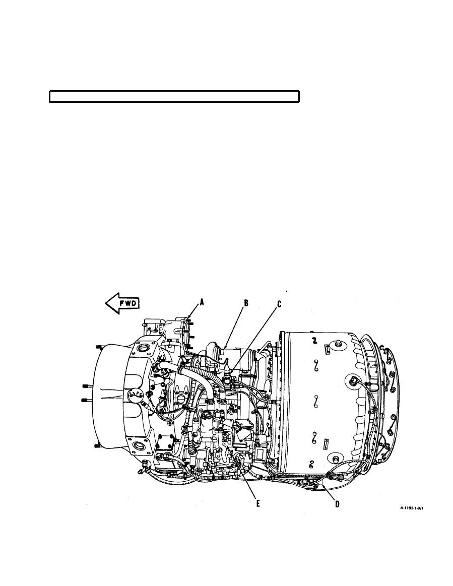
Get to know your engine. The major components are listed and keyed in the following diagrams.
A
STARTER DRIVE ASSEMBLY. Mounts at the 12-o'clock position on the inlet housing and
provides the mounting pad for the starter. Internally connects to a shaft which is
connected by gearing to the compressor rotor.
B
MAIN FUEL FILTER. Filters fuel prior to delivery to the engine fuel control. Provides a visual
indication when it is close to bypassing its element because of clogging.
C
STARTING FUEL SOLENOID VALVE. Controls fuel flow to the starting fuel primer tube and
start fuel nozzles. Activated by airframe-mounted switch.
D
FLOW DIVIDER. Mounts at the bottom of the combustion section. Divides fuel flow from in-line
fuel filter into primary and secondary flows to the main fuel manifolds.
E
FUEL CONTROL. Mounts on the accessory drive gearbox. Isa hydromechanical device contain-
ing a fuel pump, gas producer and power turbine speed governors, an acceleration
and deceleration control, an air-bleed signal mechanism, and a fuel shutoff valve.
1-5
