ARMY
TM 5-6115-612-34
NAVY
AG-320B-MME-00
8-4. OVERHAUL OF TURBINE ASSEMBLY.
(cont)
a. Disassembly (cont).
(6)
Place turbine assembly in fabricated tool
(FT-21616, Figure 8-8). This will secure the turbine
wheel (20, Figure 8-6) to prevent rotation.
(7)
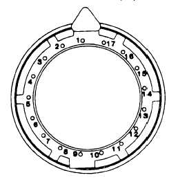
On front of compressor inlet housing (3),
remove nut (10) and washers (11 and 12) that secure
bolts in the 1, 4, 7, 10, 13, and 16 positions (see Figure
8-7) Remove bolts (13, Figure 8-6) from diffuser (2).
WARNING
To prevent injury, ensure that insulated
gloves are worn when handling dry Ice
and cold parts.
(8)
If necessary, place dry ice in diffuser. Wait
approximately ten minutes or until diffuser is well frosted.
Use soft flame to heat outside of compressor inlet
housing Carefully pull diffuser out of housing.
CAUTION
Care should be taken not to damage
shaft. Once drill penetrates nut, STOP
DRILLING!
(9)
Using a 0.125 inch ( 32 cm) drill bit, drill
out staked portion of nut.
NOTE
Speed pickup nut is staked in place.
Once removed, it is NOT reusable.
(10) Using fabricated tool (FT-21368, Figure
8-9) remove and discard speed pickup nut (14, Figure 8-
6)
CAUTION
To remove the turbine wheel, it may be
necessary to use a non-metallic hammer
Damage to the turbine wheel may occur.
NOTE
The turbine wheel assembly consist of
turbine wheel (20), labyrinth seal (19),
and bearing (18)
(11) Remove and discard retainer nut (15) and
key washer (16) Remove turbine wheel assembly from
compressor inlet housing (3)
(12) Remove two antirotation pins (17) from
turbine wheel assembly
(13) Using a bearing puller, remove bearing (18)
from turbine wheel (20) Discard bearing
(14) Using a bearing puller, remove labyrinth
seal (19) from turbine wheel (20) Inspect labyrinth seal
(19) for damage.
Figure 8-7. Compressor Inlet Housing Bolt Patter
Change 4 8-21