
TM 1-2840-252-23-3
G-58 SYSTEM TOGGLES BETWEEN PRIMARY AND REVERSIONARY MODE EXPANDED INSTRUCTIONS
Refer to numbered steps in figure 144.
Step 2.
Check harness connector PL3 (figure 201) at DECU for tight connection.
Step 3.
Disconnect connector PL3 to check pins and sockets.
Step 5.
With PL3 disconnected and primary mode selected, check resistance of primary/reversionary switch at
harness PL3 connector sockets x and e (figure 202). Limit is > 50K . With reversionary mode selected,
1
check resistance again. Limit is <50 .
Step 6.
Before tightening harness connector PL3, be sure that keyway in harness connector is aligned with
keyway in component connector.
Step 10.
Refer to manufacturer's procedure for diagnosing and replacing harness.
Step 12.
Refer to manufacturer's procedure for diagnosing and replacing switch or harness.
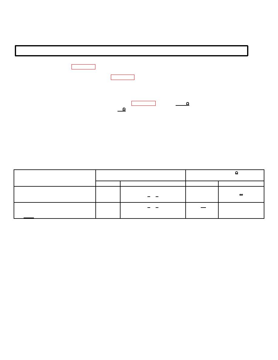
RESISTANCE-CHECK SUMMARY
Resistance ( )
Connector
Component
No.
Contacts
Limits
Nominal*
Cockpit Primary/Reversionary Switch
PL3
x&e
>150K
Primary
Reversionary
PL3
x&e
<50
1
*At 25
C
G-132
