
TM 1-2840-252-23-3
G-43
FAULT CODES C1-C3, C5-C8, COMMUNICATION LINE FAULTS EXPANDED INSTRUCTIONS
Refer to numbered steps in figure 129.
Step 2.
Check harness connectorPL1 (figure 201) at each DECU for tight connection.
Step 3.
Disconnect connector PL1 at each DECU to check pins and sockets.
Step 4.
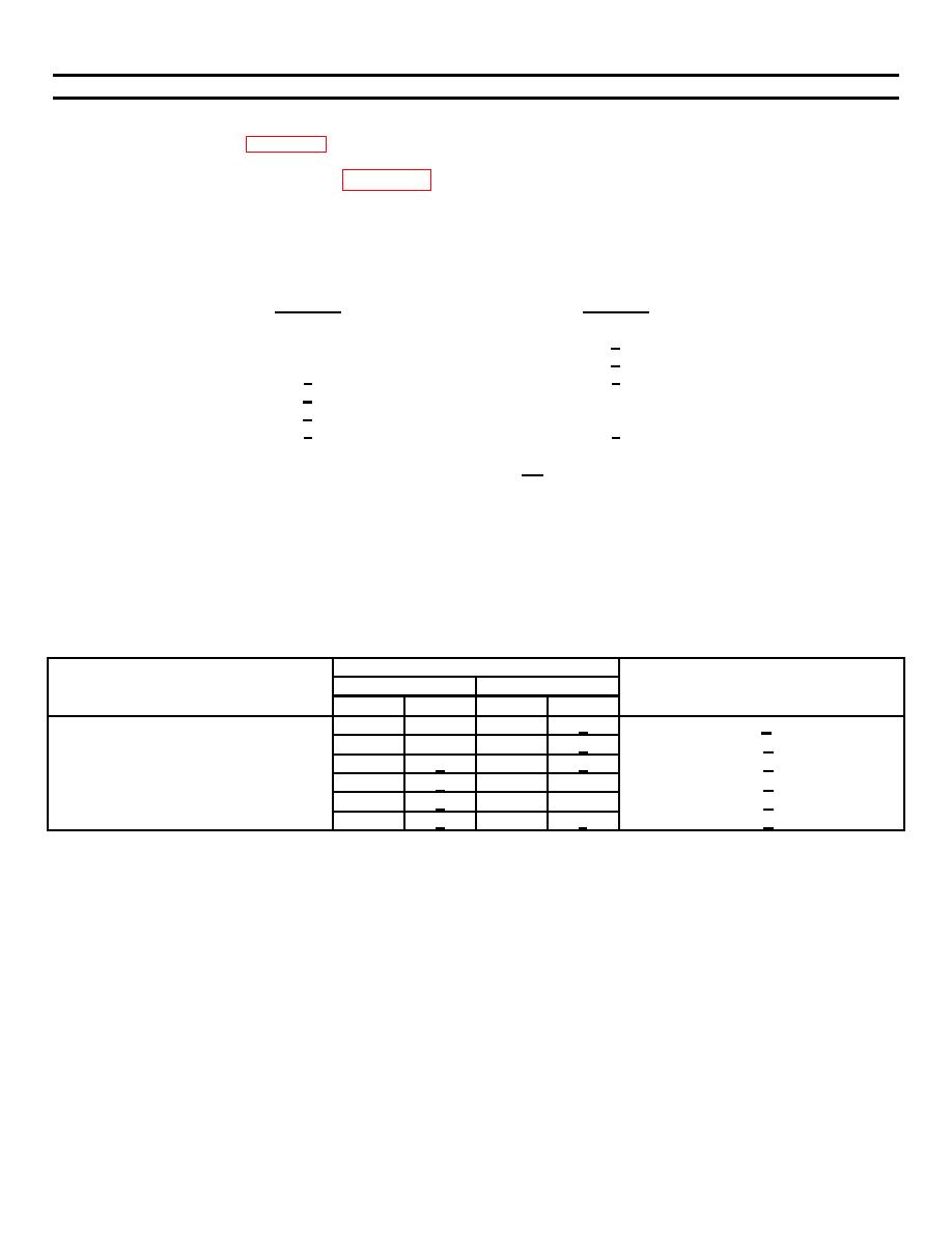
With PL1 disconnected at both DECUs, check the resistance of the harness between the two DECUs at the
following pins:
DECU #1
DECU #2
C
e
D
d
c
x
d
D
e
C
x
c
Limit in each case is < 1Ω.
Step 6.
Before tightening harness connector PL1 at each DECU, be sure that keyway in harness connector is aligned
with keyway in component connector.
Step 11.
Refer to manufacturer's procedure for diagnosing and replacing harness.
Step 13
Refer to manufacturer's procedure for diagnosing and replacing harness.
RESISTANCE-CHECK SUMMARY
Connector
DECU #1
DECU #2
Resistance Limits (Ω)
Component
No.
Contact
No.
Contact
Harness
PL1
C
PL1
e
<1
PL1
D
PL1
d
<1
PL1
c
PL1
x
<1
PL1
d
PL1
D
<1
PL1
e
PL
C
<1
PL1
x
PL1
c
<1
G-95
