
TM 1-2840-252-23-3
G-29
FAULT CODE A4, NR SENSOR EXPANDED INSTRUCTIONS
Refer to numbered steps in figure 115.
Step 2.
Check harness connector PL1 (figure 201) at DECU for tight connections.
Step 3.
Disconnect connector PL1 to check pins and sockets.
Step 5.
With PL1 disconnected, check resistance of NR sensor at harness PL1 connector sockets k and N (figure
Step 6.
Before tightening harness connector PL1, be sure that keyway in harness connectors is aligned with eyway
k
in DECU connector.
Step 9.
Refer to manufacturer's procedure for checking operation of NR sensor.
Step 12.
Refer to manufacturer's procedure for diagnosing and replacing harness.
Step 15.
Refer to manufacturer's procedure for diagnosing and replacing NR sensor.
Step 16.
Refer to manufacturer's procedure for diagnosing and replacing harness or NR sensor.
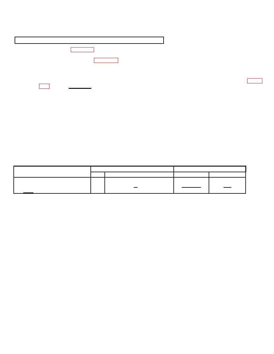
RESISTANCE-CHECK SUMMARY
Resistance (Ω)
Connector
Component
No.
Contacts
Limits
Nominal*
NR Sensor
PL1
k&N
110 - 130
120
*At 25
C
G-59
